In any PECVD system, plasma is generated by applying a strong, high-frequency electric field to a low-pressure gas inside a vacuum chamber. This applied energy accelerates free electrons, which then collide with and ionize the gas molecules, creating the reactive plasma state necessary for thin-film deposition.
The goal of PECVD is not merely to create plasma, but to use it as a low-temperature energy source. The plasma breaks down stable precursor gases into highly reactive fragments that can form a high-quality thin film without requiring the damaging high heat of traditional deposition methods.
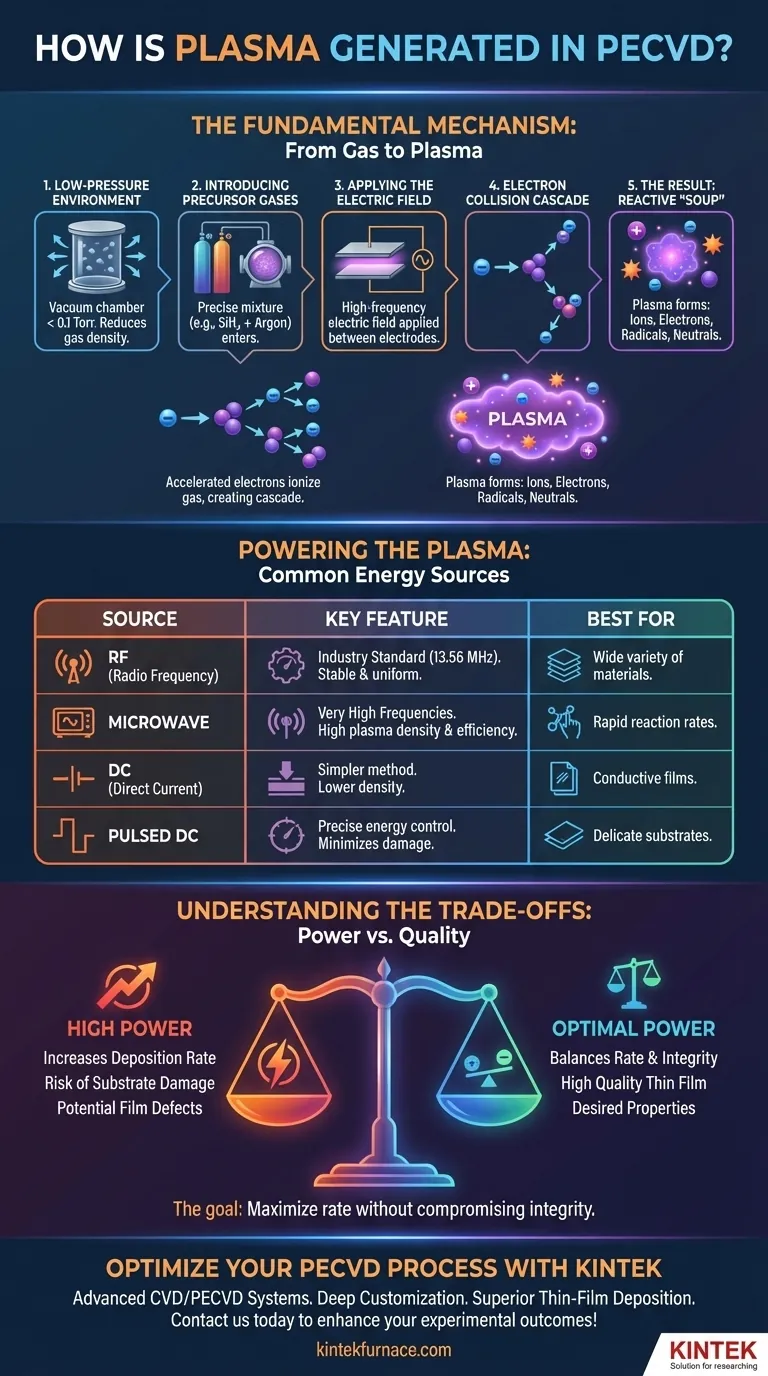
The Fundamental Mechanism: From Gas to Plasma
The creation of plasma in a PECVD reactor is a controlled, multi-step process designed to activate chemical precursors at the molecular level.
The Low-Pressure Environment
First, the process occurs within a vacuum chamber at very low pressures, typically below 0.1 Torr. This vacuum is critical because it reduces the density of gas molecules, allowing electrons to travel far enough to gain sufficient energy from the electric field before a collision.
Introducing Precursor Gases
Next, a precise mixture of precursor gases is introduced into the chamber. These are the chemical building blocks for the desired film, such as silane (SiH₄) for silicon-based films, often mixed with inert carrier gases like argon.
Applying the Electric Field
An electric field is then applied between two electrodes inside the chamber. This field, powered by an external source, provides the energy that will ultimately drive the plasma formation.
The Electron Collision Cascade
The electric field accelerates the few free electrons that are naturally present in the gas. These high-energy electrons (often 100-300 eV) collide with neutral gas molecules.
If the collision is energetic enough, it knocks an electron off the neutral molecule, creating a positively charged ion and another free electron. This process is known as ionization. The newly freed electron is also accelerated by the field, leading to a chain reaction or "cascade" that rapidly generates a dense cloud of ions and electrons.
The Result: A Reactive "Soup"
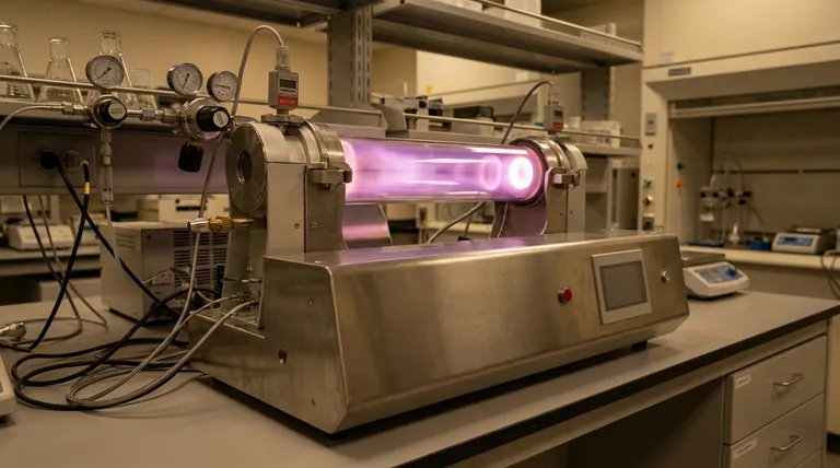
This ionized gas—a mixture of positive ions, free electrons, neutral atoms, and highly reactive molecular fragments known as radicals—is the plasma. This state, often visible as a characteristic glow, contains all the necessary energetic species to drive the deposition reaction on the substrate surface.
Powering the Plasma: Common Energy Sources
The choice of power source dictates the characteristics of the plasma and is tailored to the specific deposition requirements.
Radio Frequency (RF): The Industry Standard
The most common method uses a Radio Frequency (RF) source, typically operating at the industry-standard 13.56 MHz. RF power is highly effective at creating a stable, uniform, and sustained plasma (or "glow discharge"), making it suitable for a wide variety of materials.
Microwave Energy: A High-Frequency Alternative
Microwave sources generate plasma with even higher frequencies. This can lead to very high plasma densities and ionization efficiencies, which can be advantageous for certain processes that require rapid reaction rates.
Direct Current (DC) and Pulsed DC
Direct Current (DC) is a simpler method but generally produces lower-density plasma and is often limited to conductive materials. Pulsed DC is a more advanced technique that provides precise control over the plasma energy, which is critical when depositing films on delicate substrates to prevent damage from ion bombardment.
Understanding the Trade-offs: Power vs. Quality
Controlling the plasma is a balancing act between deposition speed and the final quality of the film. The key variable is the power applied to the electrodes.
The Role of Plasma Power
Increasing the plasma power directly increases the energy and density of the reactive species. This generally accelerates the chemical reactions, leading to a higher deposition rate.
The Risk of High Power
However, excessive power can be detrimental. It can lead to high-energy ions bombarding the substrate surface, causing physical damage or creating structural defects in the growing film. This can degrade the film's electrical or optical properties.
Balancing Deposition Rate and Film Integrity
The core challenge of process engineering in PECVD is to find the optimal power level. The goal is to maximize the deposition rate without compromising the integrity and desired properties of the final thin film.
Making the Right Choice for Your Goal
The method of plasma generation directly impacts your process outcome. Your choice should align with your primary objective.
- If your primary focus is process stability and versatility: Radio Frequency (RF) at 13.56 MHz is the established standard for producing high-quality films across a wide range of materials.
- If your primary focus is precise control over delicate materials: Pulsed DC offers superior management of plasma energy, which is essential for minimizing substrate damage during deposition.
- If your primary focus is a simpler, cost-effective setup for conductive films: Direct Current (DC) can be a viable plasma source, though it offers less control and lower plasma density.
Ultimately, mastering plasma generation is about controlling energy to drive chemical reactions with precision.
Summary Table:
| Aspect | Details |
|---|---|
| Process | Apply high-frequency electric field to low-pressure gas in vacuum chamber |
| Key Steps | Low-pressure environment, gas introduction, electric field application, electron collision cascade |
| Energy Sources | RF (13.56 MHz), Microwave, DC, Pulsed DC |
| Outcome | Creation of reactive plasma for thin-film deposition without high heat |
| Benefits | Low-temperature processing, high film quality, versatility in materials |
Optimize your PECVD process with KINTEK's advanced solutions! Leveraging exceptional R&D and in-house manufacturing, we provide diverse laboratories with high-temperature furnace systems like CVD/PECVD Systems, tailored to your unique needs. Our deep customization capabilities ensure precise plasma control for superior thin-film deposition. Contact us today to discuss how we can enhance your experimental outcomes and drive innovation in your lab!
Visual Guide
Related Products
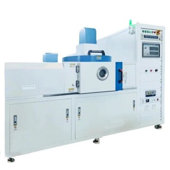
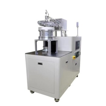
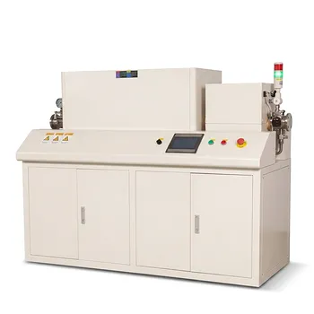
- Slide PECVD Tube Furnace with Liquid Gasifier PECVD Machine
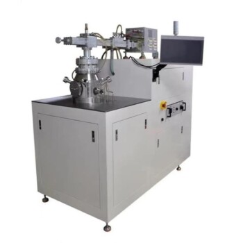
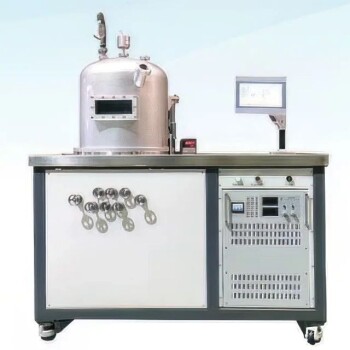
- RF PECVD System Radio Frequency Plasma Enhanced Chemical Vapor Deposition
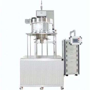
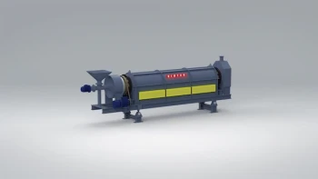
- Inclined Rotary Plasma Enhanced Chemical Deposition PECVD Tube Furnace Machine
- Inclined Rotary Plasma Enhanced Chemical Deposition PECVD Tube Furnace Machine
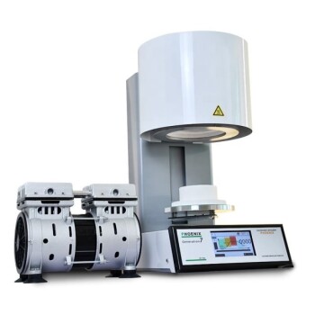
- Multi Heating Zones CVD Tube Furnace Machine for Chemical Vapor Deposition Equipment
People Also Ask
- How does a hydrogen reduction environment in an industrial tube furnace facilitate gold-copper alloy microspheres?
- What is plasma in the context of PECVD? Unlock Low-Temperature Thin Film Deposition
- What are the disadvantages of tube furnace cracking when processing heavy raw materials? Avoid Costly Downtime and Inefficiency
- What role does a Tube Furnace play in the CVD growth of carbon nanotubes? Achieve High-Purity CNT Synthesis
- What are the advantages of using a tube furnace CVD system for Cu(111)/graphene? Superior Scalability and Quality