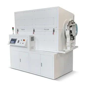
Thermal debinding is the architectural gatekeeper of ceramic manufacturing. The stage directly dictates that high-temperature laboratory furnaces must employ slow, multi-step temperature ramps and a controlled, sweeping gas flow. Without these, the rapid generation of volatile decomposition products inside a green compact will cause catastrophic blistering, warping, or cracking—destroying the part before sintering even begins.
The entire purpose of precise temperature profiling and gas flow during debinding is to match the rate of volatile gas generation with its physical escape from the part. Temperature ramps must be slow enough to let gases diffuse out, and a continuous gas sweep is essential to purge those volatiles and maintain the designed furnace atmosphere. Fail either, and you trade a usable ceramic for a microstructurally flawed reject.
The Three Stages of Thermal Debinding and Their Temperature Demands
Thermal binder removal progresses through distinct physical and chemical stages. Each stage imposes hard limits on how quickly the furnace temperature can rise, because the dominant failure mechanisms shift. Precise ramp-rate control across these zones is the single most important factor in yielding a defect-free green body.
Stage 1: Low-Temperature Softening (<200°C)
Low molecular weight additives, plasticizers, and residual solvents vaporize and diffuse through binder-filled pores. Heating must be deliberately slow here. Rapid thermal expansion of these early volatiles creates gas pressure faster than the porous network can relieve it, leading to microstructural bubbles and internal cracks. Even a slight overshoot in ramp rate can nucleate flaws that grow during later stages.
Stage 2: Rapid Thermal Degradation (200–300/400°C)
The main binder polymers thermally break down into volatile oligomers and monomers. Capillary forces rearrange the molten binder, forming nonplanar binder-vapor interfaces that shorten diffusion paths. The furnace heating rate now must balance the generation rate of volatiles against their diffusion rate out of the sample. Push too fast, and internal pressure spikes cause blistering or warping. This is often the most critical profiling window where cracking is initiated.
Stage 3: Carbon Elimination and Final Burnout (300–600°C+)
High molecular weight residues decompose through the open porosity left behind. Reaching 600°C or higher under controlled atmosphere conditions is typically required to thoroughly eliminate carbon residues. Without a prolonged dwell and active gas exchange, residual carbon can remain in the compact, altering sintering behavior, fouling furnace elements, or reacting with the final atmosphere to create unwanted carburization.
The Critical Role of Gas Flow and Atmosphere Control
Temperature ramps alone are insufficient. The gaseous byproducts from binder decomposition must be physically removed from the hot zone. A flowing gas atmosphere transforms the furnace from an oven into a controlled chemical reactor.
Sweeping Away Contaminants to Prevent Soot and Sensor Fouling
Stagnant decomposition products—especially ring-structured polymers like polystyrene—can crack into carbon soot that deposits on the work, heating elements, and atmosphere sensors. A continuous, controlled gas sweep flushes these outgassed hydrocarbons from the furnace chamber. This prevents graphite contamination on sensitive materials and stops soot from blinding oxygen probes, ensuring the furnace maintains predictable reduction or oxidation conditions.
Inert vs. Oxidizing Atmosphere Chemistry
The chosen gas not only sweeps but also defines the degradation mechanism. In inert atmospheres (nitrogen, argon), polymers break down through main-chain scission or depolymerization into volatile monomers. In an oxidizing atmosphere, degradation follows a free-radical oxidation pathway, producing low-molecular-weight compounds like H₂O, CO₂, and CO. Oxidation allows binder decomposition to occur at lower temperatures and increases the overall removal rate. However, the wrong atmosphere for the binder system or ceramic can leave carbon residues or cause unwanted pre-oxidation.
The Danger of Stagnant Gas: Residual Carbon Traps
If the gas flow is too slow or localized, partially decomposed hydrocarbons can linger and re-condense as carbon inside the pore network. Once liquid continuity breaks in the binder, isolated pockets of high-molecular-weight polymers become trapped and cannot be removed by wicking alone. Only a thermally driven burnout with a fresh gas sweep can fully eliminate these residues, preventing carbon contamination that would weaken the final sintered part.
Understanding the Trade-offs: Vacuum, Pressure, and Flow Rate
Laboratory furnaces often offer vacuum capability, but pure vacuum debinding brings its own set of compromises. Optimal outcomes usually sit at a balanced intersection.
- Pure vacuum removes binder quickly but lacks the oxygen needed for oxidative degradation and suffers from poor thermal transport, leading to large temperature gradients across the part.
- Operating with a flowing oxidizing gas at a reduced ambient pressure hits the sweet spot. It facilitates convective thermal transport for uniform temperature control, supplies oxygen to accelerate binder burnout, and still uses the sweep to carry away volatiles.
- Excessive gas flow rates can overcool the sample surface or create density gradients in the gas phase, distorting the uniform heating zone the furnace should provide. The flow must be sufficient to purge, but not so high that it compromises temperature uniformity.
Ignoring these trade-offs leads to common pitfalls: using a single fast ramp to “save time” only to crack parts, relying on a vacuum to avoid soot but forgetting that it starves the process of heat transfer, or setting a gas flow so aggressive that it creates cold spots.
Making the Right Choice for Your Goal
Your thermal debinding recipe is a direct response to the physical demands of your binder system and part geometry. Align your furnace program and gas settings with the specific outcome you need.
- If your primary focus is a defect-free microstructure in thick or complex parts: Prioritize ultra-conservative ramp rates in the 150–300°C window and use dilatometry data to identify critical expansion and shrinkage points, inserting steady dwell times where binder decomposition peaks.
- If your primary focus is reducing total cycle time without sacrificing part quality: Use an oxidizing atmosphere combined with a mild sub-ambient pressure. This accelerates binder burnout through oxidative chemistry and improves heat transfer, but always maintain a continuous gas sweep to remove the increased volume of evolved gases.
- If your primary focus is processing carbon-sensitive materials like tool steels or silicon carbide: Select a steady, moderate flow of inert or slightly reducing gas throughout the entire debinding cycle. This prevents soot formation, protects atmosphere sensors from fouling, and maintains the precise carburization/decarburization conditions the material demands.
By treating temperature profiling and gas flow not as independent parameters but as a single, synchronized system designed to manage outgassing, you can consistently transform bound powder compacts into pristine green bodies ready for high-temperature densification.
Summary Table:
| Debinding Stage | Temperature Range | Dominant Physical/Chemical Mechanism | Atmosphere & Gas Flow Demand | Primary Failure Risk |
|---|---|---|---|---|
| Stage 1: Softening | < 200°C | Low MW additives & solvents vaporize | Deliberately slow ramp rates; gentle purging | Internal micro-cracks, bubbles |
| Stage 2: Degradation | 200°C – 400°C | Polymer chain scission & volatile generation | Continuous sweep; balanced generation/diffusion | Blistering, severe warping, structural cracks |
| Stage 3: Final Burnout | 300°C – 600°C+ | Residual carbon oxidation/depolymerization | High gas exchange rate; oxidizing or inert sweep | Soot accumulation, sensor fouling, residual carbon |
Achieve flawless, defect-free green bodies with KINTEK high-performance laboratory equipment. Whether you need precise atmosphere control, vacuum capabilities, or tailored temperature profiling, KINTEK offers a comprehensive range of high-temperature furnaces—including muffle, tube, rotary, vacuum, CVD, atmosphere, dental, and induction melting systems—all fully customizable to meet your specific research and production needs.
Ready to optimize your debinding recipes and protect your critical lab hardware? Contact KINTEK today to consult with our thermal processing experts!
Related Products
- 1400℃ High Temperature Laboratory Tube Furnace with Alumina Tube
- 1700℃ High Temperature Laboratory Tube Furnace with Alumina Tube
- 1800℃ High Temperature Muffle Oven Furnace for Laboratory
- 1700℃ High Temperature Muffle Oven Furnace for Laboratory
- 1200℃ Muffle Oven Furnace for Laboratory
People Also Ask
- How does zone-melting in tube furnaces synthesize bismuth micro-wires? Master Single-Crystal Thermoelectric Growth
- How are high-temperature laboratory tube furnaces applied in long-term vacuum homogenization heat treatments for intermetallic samples?
- How are high-temp tube furnaces used to measure diffusion coefficients per Fick's law? Master Precision Annealing
- How do high-temperature laboratory tube furnaces ensure environmental stability? Precision Thermal Reduction Tips
- How are high-temperature tube furnaces applied in testing ceramic-supported alloy membranes? Insights