Substrate constraint doesn’t just limit shrinkage—it rewires the entire densification mechanism.
When co-firing multi-layer ceramics on a rigid substrate, in-plane (x–y) shrinkage is completely suppressed. All dimensional change is forced into the thickness direction. This lateral fixity creates in-plane tensile stresses that accelerate vertical densification according to the material’s viscous Poisson’s ratio. However, the same constraint also amplifies warpage from differential layer sintering, making precise temperature control and stress management the central challenge of the process.
The core dynamic: a rigid substrate converts multi‑axial shrinkage into a uniaxial problem, simultaneously speeding up thickness reduction and introducing tensile stresses that can bend or crack the stack if sintering kinetics aren’t perfectly balanced. Mastering the thermal cycle turns this constraint from a warpage risk into a tool for tight dimensional control.
The Mechanics of Constrained Thin-Film Sintering
From Three‑Dimensional Shrinkage to Uniaxial Densification
In a free‑standing compact, densification happens isotropically—all axes shrink together.
A rigid substrate eliminates that freedom completely. The film remains bonded laterally, so its x and y dimensions are fixed.
All volume reduction is forced into the perpendicular z‑axis.
This is not merely a geometric restriction; it fundamentally alters the stress state and the rate at which the material densifies.
The Role of Viscous Poisson’s Ratio and Induced Stress
With lateral strain rates locked at zero, the film develops in‑plane tensile stress.
For a material sintering by viscous flow, that stress is intimately linked to the viscous Poisson’s ratio ( \nu_p )—a measure of how much lateral constraint boosts the thickness‑direction strain.
The constrained vertical strain rate follows:
[ \epsilon_z = \frac{1 + \nu_p}{1 - \nu_p} \cdot \epsilon_f ]
Here ( \epsilon_f ) is the unconstrained free strain rate.
Because ( \nu_p ) is always less than 0.5 for a porous body, this ratio exceeds 1, meaning the film shrinks faster in z than a free film would in any single direction.
Crucially, this higher axial rate comes with a cost: the overall densification kinetics slow down because all volume change must pass through a single axis.
Consequently, constrained amorphous films often need about 25% longer thermal processing to reach full density compared to their unconstrained counterparts.
How Differential Sintering Drives Warpage in Multi-Layer Stacks
Heterogeneous Materials Create Mismatched Internal Forces
Real multi‑layer devices rarely consist of identical layers.
Each layer may have a different particle size, binder system, or composition, giving it a distinct sintering onset temperature and shrinkage rate.
When a fast‑shrinking layer is physically attached to a slow‑shrinking one, the difference in their in‑plane stresses creates a bending moment.
That moment is what causes the structure to warp or delaminate if the mismatch is left unchecked.
The Viscous Balancing Act: Temperature Profiles and Stress Relaxation
The only way to suppress this warpage is to give each layer time to relax its internal stresses before they accumulate into large‑scale deformation.
That’s where the furnace’s temperature ramp rate and uniformity come into play.
A slow, controlled ramp allows the viscous phases to deform and even out stress gradients.
A furnace with excellent thermal uniformity ensures that all regions of the stack experience the same thermal history simultaneously, preventing location‑specific stress concentrations.
For extreme cases, a sacrificial rigid substrate can be used as a temporary flat support during the entire co‑firing cycle, then removed post‑sintering.
This physically constrains all layers to the same plane, buying time for stress relaxation without dimensional drift.
Understanding the Trade‑offs
Retarded Densification Rates
Constrained films always densify slower than free compacts.
The single‑axis shrinkage restricts the available pathways for pore removal, adding to the required dwell time.
Engineers must account for this delay when scaling from monolithic pellet data to thin‑film furnace profiles.
Cutting time too short leaves residual porosity; running longer risks excessive grain growth or inter‑diffusion.
Crystalline Films and the Final Density Ceiling
When a film sinters by solid‑state diffusion instead of viscous flow, constraint plays an even harsher role.
As grains coarsen into a columnar microstructure spanning the film thickness, lateral constraint prevents further densification.
The result is a final density well below theoretical, because the film accommodates further free‑energy reduction by deepening grain‑boundary grooves rather than compacting.
This can initiate film breakup into isolated islands or pinholes if not managed carefully.
Dewetting and Microstructural Instability
Columnar grains pinned to a rigid substrate can become unstable at high temperatures.
Grain‑boundary grooving eats into the film’s thickness until the continuous layer tears apart—a process known as dewetting.
This is a critical failure mode in thin functional layers for capacitors or sensors.
Precise atmosphere control and optimized heating rates in the furnace can reduce groove deepening and preserve film continuity.
Making the Right Choice for Your Goal
- If your primary focus is flat, warp‑free multilayer structures: Use a slow, uniform thermal ramp and, for high‑risk stacks, incorporate a sacrificial rigid substrate that is removed after sintering. Match the sintering kinetics of adjacent layers as closely as possible.
- If your primary focus is maximum film density: Plan for approximately 25% longer soak times than would be needed for a free compact. For crystalline films, keep the film thickness below the point where columnar grains dominate, or accept the lowered endpoint density and design around it.
- If your primary focus is avoiding delamination or cracks: Prioritize stress relaxation by controlling the cooling phase and using a furnace with high thermal uniformity. Thin, porous layers sintered at lower temperatures can act as built‑in compliant interlayers.
- If your primary focus is preventing microstructural defects like pinholes: Limit grain growth through fast heating to final temperature while maintaining atmosphere control; this suppresses groove deepening and dewetting in the final sintering stage.
Your furnace is more than a heat source—it’s the governor of stress, dimension, and integrity across every layer in the stack. Align its profile with the viscous and microstructural rules of constrained sintering, and you turn an inherent liability into a reproducible manufacturing advantage.
Summary Table:
| Aspect / Dynamic | Mechanism & Effect | Furnace & Process Solution |
|---|---|---|
| Dimensional Shrinkage | In-plane (x–y) strain locked at zero; 100% vertical (z-axis) strain | Plan for ~25% longer thermal dwell times to compensate for slower kinetics |
| Stress & Warpage | Mismatched sintering kinetics induce severe bending moments | Utilize precise ramp rates, uniform heating, or sacrificial substrates |
| Final Density Limit | Solid-state diffusion forms columnar grains, capping maximum density | Fine-tune thermal profiles to suppress excessive grain-boundary grooving |
| Microstructural Integrity | High thermal stress can trigger grain dewetting and pinholes | Control furnace atmosphere and rapid-heating stages to maintain film continuity |
Eliminate Co-Firing Defect Rates with KINTEK Thermal Solutions
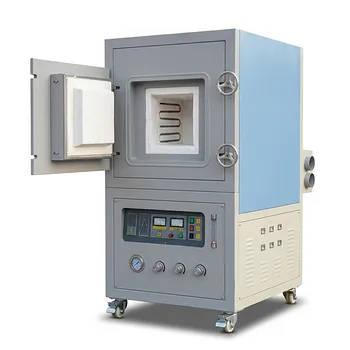
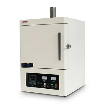
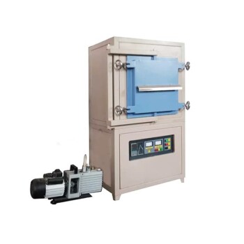
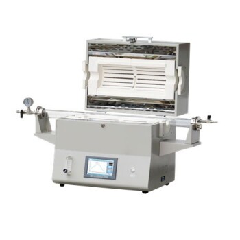
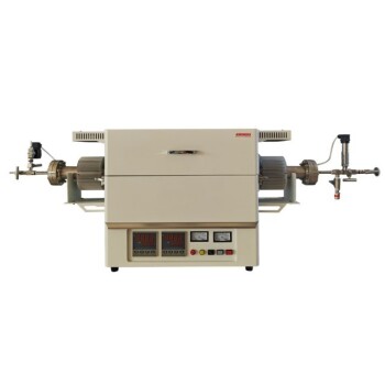
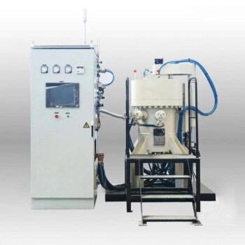
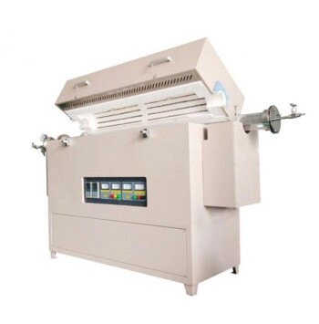
Controlling stress, shrinkage, and warpage in multi-layer ceramic substrates demands precise thermal uniformity and tailored sintering environments. KINTEK specializes in advanced laboratory equipment and customizable high-temperature furnaces—including atmosphere, vacuum, tube, muffle, and CVD systems—engineered to give you absolute control over your thermal cycles.
Whether you are scaling thin-film ceramics or developing complex multi-layer stacks, our tailored high-temperature furnace solutions help you prevent delamination and achieve optimal density. Contact KINTEK today to optimize your ceramic sintering process!
Related Products
- High Temperature Muffle Oven Furnace for Laboratory Debinding and Pre Sintering
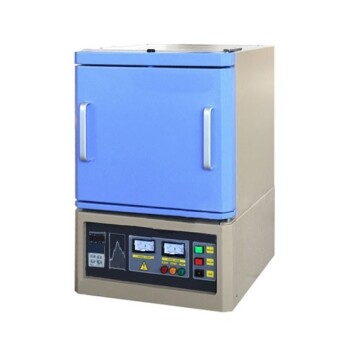
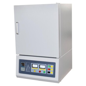
- 1200℃ Muffle Oven Furnace for Laboratory
- 1700℃ Controlled Inert Nitrogen Atmosphere Furnace
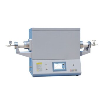
- 1400℃ High Temperature Laboratory Tube Furnace with Alumina Tube
- 1700℃ High Temperature Laboratory Tube Furnace with Alumina Tube
People Also Ask
- What thermal phenomena occur during polymer binder burnout in ceramic green bodies? Lab Furnace Guide
- Why is controlled heat treatment in a muffle furnace necessary for calcined clay? Achieve Optimal Pozzolanic Activity
- What role does a high-temperature muffle furnace play in STFO synthesis? Achieve Pure Perovskite Results
- How does a high-temperature muffle furnace facilitate the formation of LaNbxAl1−xO3+δ perovskite structures? Key Roles
- What role does a high-temperature muffle furnace play in the multi-stage synthesis of Li0.5MnFe1.5O4? Key to Pure Spinel