The simple answer is that sensor placement creates a critical and predictable offset. A pyrometer aimed at the outer die wall will always read significantly lower than the internal sample temperature—often by 100 °C or more at a 1200 °C setpoint. A thermocouple placed within 5 mm of the sample, or an axial measurement at the punch bottom, provides a reading that is much closer to the material's true temperature, enabling precise control over densification and preventing accidental overheating.
The core challenge is physics, not instrument failure. The die wall loses heat continuously to its surroundings, creating a steep thermal gradient from the sample core outward. Your choice of measurement point is effectively a choice about which part of that gradient you want to control. Mastering this means calibrating your sensor's offset, not trying to eliminate it.
The Physics of the Thermal Gradient
The reading difference isn't just a minor error; it's a fundamental consequence of how heat flows in a pressurized, high-temperature die. Understanding this flow pattern is the first step to accurate process control.
Where the Heat Dissipates
In any lab sintering furnace, the specimen is the intended heat source or target. However, the tooling surrounding it—the graphite die and punches—is not a perfect insulator.
The outer die wall is a primary radiator and convection surface. It constantly dissipates energy into the furnace chamber. This creates a persistent, dynamic state where the surface temperature at the measurement point lags behind the peak temperature at the core of your sample. This is the root cause of the 100 °C+ underestimation.
The Internal vs. External Reality
The internal temperature is what drives diffusion, grain growth, and densification. An external sensor only reports the boundary condition of the heat sinking element. This mismatch is not constant; it widens at higher temperatures as radiative heat loss (proportional to T⁴) skyrockets, while the thermal conductivity of the die material often decreases.
The result is a non-linear offset. A calibration at 600 °C will not be valid for a process at 1200 °C or 1600 °C.
Measuring at the Die Wall: The Case of the Pyrometer
The Problem of Apparent Temperature
When an optical pyrometer sights the outer die wall, it reads the surface's radiation. This "apparent temperature" is always lower than the internal, true temperature during heating. The exact offset depends heavily on applied pressure (which changes contact resistance), heating rate, and the emissivity settings on your pyrometer.
This method is safe—it keeps the sensor out of the hot zone. But it trades accuracy for convenience. You are controlling the process based on a proxy signal, making it essential to correlate the die wall temperature with the sample's melting point or phase changes using a calibration curve.
The Impact of High Heating Rates
This offset is magnified under rapid heating, such as the 100 to 600 K/min rates used in spark plasma sintering (SPS). In these furnaces, the current distribution can make the punches hotter than the die wall. The thermal inertia of the sample and die means the core cannot heat instantaneously, and the lag becomes a gulf.
Trying to push to 1200 °C in minutes while looking only at the die wall is like trying to judge the speed of a car by watching the smoke from its tires. By the time the surface signal catches up, the core might have already overshot, causing grain growth or melting.
Measuring Near the Sample: The Case of the Punch or Axial Thermocouple
Accessing True Process Limits
Placing a thermocouple in the punch bottom, just behind the pressure pad and within 5 mm of the specimen, or embedding it in the die wall directly beside the powder, dramatically closes this measurement gap.
This sensor position sees the heat flux coming out of the sample, not the heat lost from the die periphery. The reading is therefore tightly coupled to the densification kinetics. This level of accuracy allows you to operate safely at the upper boundary of your material's thermodynamic stability without fear of an unknown 100 °C overshoot causing unintended liquid phase formation.
Preventing Microstructural Damage
Near-sample measurements enable a tight feedback loop. Because the sensor detects temperature changes in the sample almost instantly, the operator can avoid the "thermal inertia overshoot" common with die wall control.
The consequence is direct: uniform microstructures. When you eliminate the hidden temperature swing, you prevent the dual problem of a too-cold surface (leaving residual porosity) and an overheated core (coarsening grains). This is essential for nanocrystalline or metastable materials, where a 50 °C fluctuation can destroy the desired phase.
Understanding the Trade-offs
The False Economy of Simplicity
The trade-off is not about cost or complexity alone; it's about the failure mode you are willing to accept. An external pyrometer is non-contact and robust, but its failure mode is silent—a systematic error that can grow over a campaign as the sight glass fogs or the die emissivity changes.
A near-sample thermocouple gives ground truth, but it introduces a mechanical risk. A poorly sealed port can cause a pressure boundary failure, and a broken tip during a run can damage a die set worth thousands of dollars.
The Calibration Imperative
There is no single "correct" sensor for all purposes. The key is treating sensor placement as a process variable that demands a formal offset study.
- For the Die Wall Pyrometer: You must run a calibration with a reference melt or phase transformation at your target heating rate to empirically map the offset.
- For the Punch Thermocouple: You must account for the thermal conductivity of the electrode itself, which can act as a heat sink, pulling the reading a few degrees below the absolute core peak.
Making the Right Choice for Your Lab Process
Your primary process goal should dictate your sensor strategy. The right choice is the one that targets the parameter you actually need to control.
- If your primary focus is phase evolution and microstructure integrity: Use a punch or near-sample thermocouple. The direct correlation between reading and sample state is non-negotiable for preventing grain growth in nanomaterials or precisely hitting a narrow sintering window.
- If your primary focus is high-throughput screening or system protection: Use a die wall pyrometer for its non-contact, robust setup. However, you must accept that the "setpoint" is a relative indicator and meticulously map the offset at every heating rate to avoid permanently skewing your property data.
- If your primary focus is sintering large, complex parts: Never rely on a single sensor. Cross-reference a die wall pyrometer with an at-depth thermocouple to quantify the thermal lag explicitly, creating a multi-zone model that compensates for the size-dependent gradient, ensuring the entire component densifies uniformly.
Your furnace's sensor reading is only useful when you know exactly what it cannot see.
Summary Table:
| Feature / Parameter | Die Wall Pyrometer | Punch / Near-Sample Thermocouple |
|---|---|---|
| Measurement Location | Outer graphite die surface | Punch bottom / within 5mm of sample |
| Accuracy vs. Core Temp | High offset (reads ~100°C+ lower at 1200°C) | Highly accurate (near true sample temp) |
| Thermal Response | High lag (magnified at rapid heating rates) | Immediate feedback on core heat flux |
| Main Advantage | Non-contact, durable, zero mechanical contact risk | Prevents overheating & grain growth |
| Primary Risk / Drawback | Silent drift (sight glass fogging, emissivity shifts) | Mechanical wear, port/die breakage risk |
| Recommended Use Case | High-throughput screening, system protection | Microstructure control, phase stability studies |
Elevate Your Thermal Processing Precision with KINTEK
Don't let uncalibrated thermal gradients compromise your material research or sintering density. KINTEK specializes in premium laboratory equipment and consumables, offering a comprehensive range of customizable high-temperature furnaces—including muffle, tube, rotary, vacuum, CVD, atmosphere, dental, and induction melting furnaces engineered for superior thermal control.
Whether you need custom sensor ports, dual-monitoring systems, or expert guidance on high-temperature process parameters, our team is here to support your lab's exact requirements.
👉 Contact KINTEK Today to Upgrade Your High-Temperature Lab Furnaces
Related Products
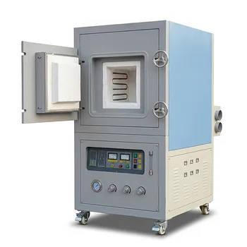
- High Temperature Muffle Oven Furnace for Laboratory Debinding and Pre Sintering
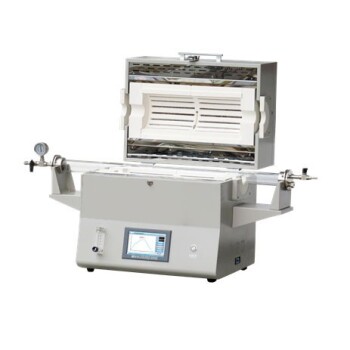
- 1400℃ High Temperature Laboratory Tube Furnace with Alumina Tube
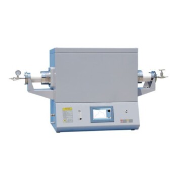
- 1700℃ High Temperature Laboratory Tube Furnace with Alumina Tube
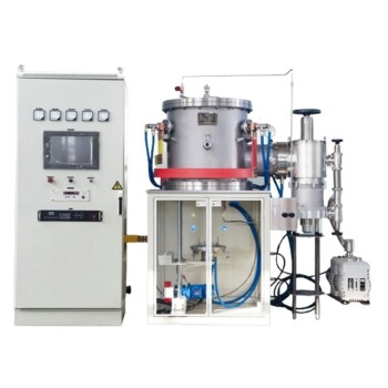
- 2200 ℃ Tungsten Vacuum Heat Treat and Sintering Furnace
- 1800℃ High Temperature Muffle Oven Furnace for Laboratory
People Also Ask
- What thermal phenomena occur during polymer binder burnout in ceramic green bodies? Lab Furnace Guide
- What role does a high-temperature muffle furnace play in STFO synthesis? Achieve Pure Perovskite Results
- Why is controlled heat treatment in a muffle furnace necessary for calcined clay? Achieve Optimal Pozzolanic Activity
- How does a high-temperature muffle furnace facilitate the formation of LaNbxAl1−xO3+δ perovskite structures? Key Roles
- What role does a high-temperature muffle furnace play in the multi-stage synthesis of Li0.5MnFe1.5O4? Key to Pure Spinel