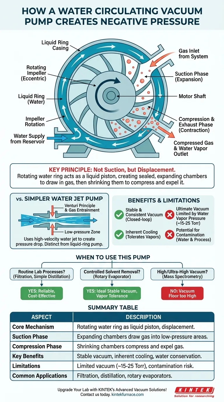
At its core, a water circulating vacuum pump creates negative pressure by using a rotating impeller to form a dynamic ring of water inside a pump casing. This ring of water acts as a liquid piston. As the impeller turns, it creates expanding pockets of space that draw gas in from your system, and then shrinking pockets that compress and expel that gas, progressively lowering the pressure.
The key principle is not suction but displacement. The pump uses a rotating ring of water to create sealed, expanding chambers. Gas from your system flows into these low-pressure chambers, is trapped, and then compressed and ejected, progressively lowering the system's pressure.
The Core Mechanism: The Liquid-Ring Piston
The most common type of water circulating vacuum pump functions as a liquid-ring pump. This design is elegant because the water serves as the sealant, the piston, and a coolant all at once.
Forming the Water Ring
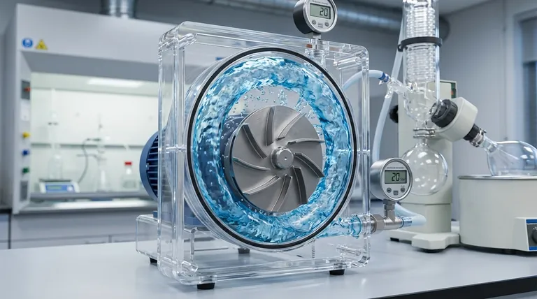
When the pump is started, a motor spins an impeller with multiple blades inside a cylindrical casing. Centrifugal force throws the water supplied from the reservoir outward, forcing it to form a concentric ring that follows the inner wall of the pump casing.
The Role of the Eccentric Impeller
The crucial design feature is that the impeller is mounted eccentrically (off-center) within the casing. This means that while the water ring is perfectly centered, the impeller hub is closer to the casing wall at the bottom and farther away at the top.
The Suction Phase (Expansion)
As a pair of impeller blades rotates through the top half of the casing, the distance between the impeller hub and the liquid ring steadily increases. This expands the volume of the space, or "chamber," trapped between the blades and the water.
This expansion creates a drop in pressure. The chamber is aligned with an inlet port connected to your vacuum system, and gas flows from the higher-pressure system into this newly created low-pressure space.
The Compression and Exhaust Phase (Contraction)
As the same chamber continues its rotation into the bottom half of the cycle, the eccentric mounting causes the space to shrink. The water ring is now moving closer to the impeller hub, compressing the trapped gas.
This compression increases the gas pressure above atmospheric pressure. Once the chamber aligns with the exhaust port, this compressed gas is forced out of the pump. The cycle then repeats with every rotation, continuously removing gas from the system.
Distinguishing from a Simpler Water Jet Pump
Some references use the term "fluid jet technology," which describes a different, simpler mechanism known as a water aspirator or eductor-jet pump. It's important to know the difference.
The Venturi Principle
This simpler design works by forcing a high-velocity jet of water through a constricted nozzle (a venturi).
Creating the Pressure Drop
According to Bernoulli's principle, the high speed of the fluid in the constriction leads to a significant drop in its static pressure. This creates a low-pressure zone around the water jet.
Gas Entrainment
A side port connected to the vacuum system is positioned at this low-pressure point. Gas from the system is drawn in (entrained) and carried away with the stream of water, creating a vacuum. While also a "water vacuum pump," this is distinct from the more robust mechanical liquid-ring pump.
Understanding the Trade-offs and Key Benefits
A water circulating pump is a workhorse in many labs for specific reasons, but it comes with inherent limitations.
Benefit: Constant Recirculation
Unlike a simple aspirator attached to a faucet, a circulating pump uses a closed-loop reservoir. This conserves a significant amount of water and, more importantly, provides a stable and consistent vacuum level that is not dependent on fluctuating municipal water pressure.
Benefit: Inherent Cooling
The circulating water absorbs the heat generated from gas compression. This makes the pump tolerant of condensable vapors (like solvents) that might damage other types of vacuum pumps.
Limitation: Ultimate Vacuum Level
The deepest vacuum a water pump can achieve is limited by the vapor pressure of the water itself. As the system pressure approaches the water's vapor pressure (at its current temperature), the water will begin to boil. This vapor contributes to the system pressure, establishing a floor for the vacuum level, typically around 15-25 Torr (0.02-0.03 bar).
Limitation: Potential for Contamination
The water in the reservoir can become contaminated by the vapors it pulls from the chemical process. Conversely, water vapor from the pump will inevitably enter the vacuum system, which may be undesirable for highly moisture-sensitive applications.
How to Apply This to Your Project
Understanding the mechanism helps you decide if this pump is the right tool for your specific scientific goal.
- If your primary focus is routine lab processes: like filtration, simple distillation, or drying glassware under vacuum, this pump provides a reliable, cost-effective solution without wasting water.
- If your primary focus is controlled solvent removal: using an instrument like a rotary evaporator, the pump's stable, moderate vacuum is ideal and its ability to handle solvent vapors is a major advantage.
- If your primary focus is achieving high or ultra-high vacuum: for applications like mass spectrometry or surface science, this pump is unsuitable; its vacuum floor is far too high.
By using a recirculating ring of water as its core mechanism, this pump provides a robust and practical solution for generating moderate vacuum in a laboratory setting.
Summary Table:
| Aspect | Description |
|---|---|
| Core Mechanism | Uses a rotating impeller to form a dynamic water ring that acts as a liquid piston, creating expanding and contracting chambers for gas displacement. |
| Suction Phase | Expanding chambers draw gas from the system into low-pressure areas via inlet ports. |
| Compression/Exhaust Phase | Shrinking chambers compress and expel gas through exhaust ports, progressively lowering pressure. |
| Key Benefits | Constant recirculation for stable vacuum, inherent cooling for vapor tolerance, and water conservation. |
| Limitations | Ultimate vacuum limited by water vapor pressure (~15-25 Torr), potential for contamination from vapors or moisture. |
| Common Applications | Routine lab processes like filtration, distillation, and solvent removal in rotary evaporators. |
Upgrade Your Lab with KINTEK's Advanced Vacuum Solutions!
Leveraging exceptional R&D and in-house manufacturing, KINTEK provides diverse laboratories with advanced high-temperature furnace solutions and reliable vacuum systems. Our product line, including Muffle, Tube, Rotary Furnaces, Vacuum & Atmosphere Furnaces, and CVD/PECVD Systems, is complemented by strong deep customization capability to precisely meet unique experimental requirements. Whether you need efficient vacuum pumps for filtration or tailored furnace setups, we deliver performance and precision to enhance your research and productivity.
Contact us today to discuss how our solutions can optimize your laboratory processes and achieve your scientific goals!
Visual Guide
Related Products
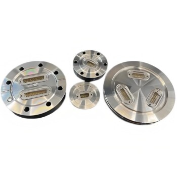
- Ultra-High Vacuum Flange Aviation Plug Glass Sintered Airtight Circular Connector for KF ISO CF
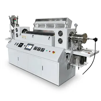
- Vacuum Sealed Continuous Working Rotary Tube Furnace Rotating Tube Furnace
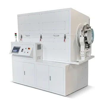
- Laboratory Vacuum Tilt Rotary Tube Furnace Rotating Tube Furnace
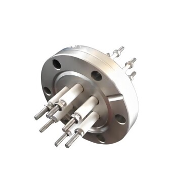
- CF KF Flange Vacuum Electrode Feedthrough Lead Sealing Assembly for Vacuum Systems
People Also Ask
- What role does a closed pressure vessel play during the carbonation of gamma-C2S? Unlock Rapid Mineralization
- What is the function of a Teflon-lined stainless steel autoclave in the hydrothermal synthesis of Bi2O3 precursors?
- Why is a PTFE-lined stainless steel autoclave used for Ni12P5 synthesis? Key Benefits for Nanomaterial Production
- What role does a Teflon-lined stainless steel autoclave play in the hydrothermal synthesis of PtLaOx@S-1 catalysts?
- Why is an Ultra-High Vacuum (UHV) System Required for In2Se3? Achieving Atomic-Level Ferroelectric Clarity