Rheological measurements directly map the sweet spot where a ceramic suspension achieves the highest possible solids loading while remaining processable. By plotting viscosity against shear rate and dispersant concentration, you precisely identify the additive percentage that breaks down particle agglomerates and minimizes flow resistance. This optimized, low-viscosity slurry casts or tapes into a green body with near-perfect particle packing, slashing the volumetric shrinkage and internal stresses that would otherwise cause cracking, warping, and density gradients during high-temperature furnace sintering.
The surface-level question is about linking viscosity tests to furnace outcomes, but the deeper need is to eliminate unpredictable sintering defects before the kiln ever fires. The core insight: a slurry’s viscosity profile predicts its green density and homogeneity with remarkable accuracy. Nail the rheology, and you shift the burden of perfection from the furnace soak zone back to the mixing bench.
The Direct Link Between Slurry Rheology and Sintering Success
Viscosity measurements are not just quality checks—they are a predictive tool that governs how a part survives the furnace. A well-dispersed suspension with optimized flow characteristics builds a green body that behaves predictably during binder burnout, thermal ramping, and final densification.
Viscosity as a Window into Dispersion Quality
Every ceramic suspension has a critical dispersant concentration where agglomerates are broken apart and particles are uniformly coated. Rheology reveals this point. As you titrate dispersant into the slurry, viscosity drops sharply until a plateau is reached—this is where electrostatic or steric stabilization dominates and particle-particle friction is minimized. Operating at this viscosity minimum ensures fine, evenly distributed pores and consistent particle contacts in the green compact, eliminating the soft agglomerates that would otherwise act as defect initiation sites during high-temperature furnace processing.
Maximizing Solids Loading Without Sacrificing Flow
The ultimate goal is to push the solid volume fraction as high as possible while maintaining a viscosity low enough for your shaping method (slip casting, tape casting, etc.). Rheological curves of viscosity versus solids loading reveal a characteristic “percolation threshold.” Below this threshold, viscosity rises gently; above it, viscosity skyrockets. By measuring this transition, you can pin the solids content just before the cliff, achieving a high green packing density that directly minimizes the total shrinkage the part will undergo in the furnace.
How Green Body Integrity Translates to Sintering Performance
High-temperature furnace sintering amplifies every micro-scale inconsistency that rheological tuning can prevent. A uniform green body is the single greatest guarantee of a defect-free fired part.
Minimizing Volumetric Shrinkage and Warping
When a green body has a high packing density, there is simply less inter-particle void space to eliminate during sintering. Reduced shrinkage is a direct consequence of maximized solids loading, and it is the most powerful defense against warping. Lower shrinkage means lower internal stress development as the part heats in a muffle or tube furnace, significantly reducing the risk of cracking, slumping, or distortion across complex geometries.
Preventing Microstructural Defects
A low-viscosity, well-dispersed slurry produces a green body free of hard agglomerates and density gradients. During furnace processing—especially during the critical binder burn-out stage—this uniformity ensures that escaping gases find an open, consistent percolation network of pores. If viscosity measurements indicated a flocculated or poorly stabilized suspension, the resulting green body would contain dense clusters. These clusters densify at different rates during the peak sintering hold, causing differential shrinkage, internal micro-cracking, and locked-in porosity that no amount of furnace atmosphere control can later fix.
Understanding the Trade-offs in Rheological Optimization
Rheological optimization is not simply about chasing the lowest viscosity. Critical compromises exist, and the data from your measurements will guide you to the best balance.
High Solids Loading Versus Processability
You can push solids loading to the extreme, but only if the slurry’s yield stress and apparent viscosity remain compatible with your mold filling or tape-blading process. A slurry that is too thick will entrap air bubbles, fill intricate mold cavities incompletely, or resist self-leveling. The rheometer quantifies this limit so you can make a data-driven decision: accept a slightly lower solids fraction to guarantee a bubble-free, fully filled green body, which often results in a better final part than a theoretically denser but process-starved one.
The Pitfall of Over-Stabilization
Adding too much dispersant, even if viscosity appears stable, can introduce a different set of problems. Excess free polymer or unadsorbed electrolytes can foam, segregate during drying, or leave behind excessive carbon residue that complicates binder burnout in an inert atmosphere furnace. Rheological measurements at multiple frequencies (oscillatory tests) can sometimes detect the onset of depletion flocculation or structural weakness in the gel network, warning you to back off even if the viscosity number looks good.
Making the Right Choice for Your Process
Your specific furnace and forming method dictate which rheological benchmark matters most. Use the following goal-oriented priorities to interpret your viscosity curves effectively.
- If your primary focus is producing crack-free, large-format parts: Prioritize the minimum viscosity point that guarantees full de-agglomeration, even if that means a marginal sacrifice in absolute solids loading. A homogeneous green body with uniform shrinkage is paramount.
- If your primary focus is achieving near-net shape with minimal furnace distortion: Maximize solids loading to the rheological percolation threshold—right where viscosity begins its steep climb. This minimizes shrinkage and warping potential during the critical early heating stages.
- If your primary focus is reliable binder burnout in thick cross-sections: Ensure the low-shear viscosity plateau indicates a stable, open network, and combine this with zeta potential measurements far from the isoelectric point. This guarantees interconnected porosity that lets gases escape without creating pressure spikes in the furnace.
- If your primary focus is repeatable high-density final parts: Establish a viscosity specification range that correlates with a consistent green density above 60%, then lock in your solids loading and dispersant concentration. Use the rheometer as a go/no-go gate before any material ever enters the high-temperature furnace.
A rheometer on a bench is your ultimate pre-furnace process insurance; every unit of effort you invest in optimizing slurry flowability comes back tenfold in the final density, strength, and straightness of your sintered ceramic component.
Summary Table:
| Rheological Focus | Parameter Measured | Green Body Impact | Sintering Outcome |
|---|---|---|---|
| Dispersion Quality | Critical dispersant concentration | De-agglomeration & uniform pore distribution | Prevents localized density gradients and micro-cracks |
| Solids Loading | Viscosity percolation threshold | Maximized particle packing density | Minimizes volumetric shrinkage and warping |
| Processability | Yield stress & low-shear viscosity | Complete mold filling without bubble entrapment | Prevents structural voids and geometric distortion |
| Stability Check | Oscillatory / gel network strength | Clean binder burnout without organic residue | Prevents gas pressure buildup during furnace ramping |
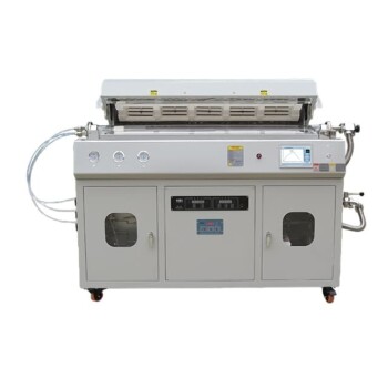
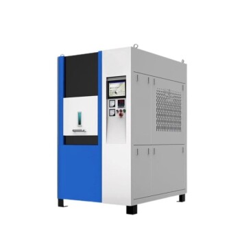
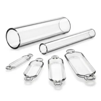
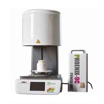
Eliminate sintering defects and achieve superior component density with high-performance laboratory equipment from KINTEK. As specialists in advanced thermal processing, KINTEK offers a comprehensive range of customizable high-temperature furnaces—including muffle, tube, rotary, vacuum, CVD, atmosphere, dental, and induction melting systems—tailored to meet your exact ceramic research and production requirements. Boost your lab's precision and product yield—contact KINTEK today to discuss your application with our technical experts!
Related Products
- High Temperature Muffle Oven Furnace for Laboratory Debinding and Pre Sintering
- Multi Heating Zones CVD Tube Furnace Machine for Chemical Vapor Deposition Equipment
- Vacuum Dental Porcelain Sintering Furnace for Dental Laboratories
- Vertical Laboratory Quartz Tube Furnace Tubular Furnace
- Multi Zone Laboratory Quartz Tube Furnace Tubular Furnace
People Also Ask
- What thermal phenomena occur during polymer binder burnout in ceramic green bodies? Lab Furnace Guide
- Why is controlled heat treatment in a muffle furnace necessary for calcined clay? Achieve Optimal Pozzolanic Activity
- What role does a high-temperature muffle furnace play in STFO synthesis? Achieve Pure Perovskite Results
- How does a high-temperature muffle furnace facilitate the formation of LaNbxAl1−xO3+δ perovskite structures? Key Roles
- What role does a high-temperature muffle furnace play in the multi-stage synthesis of Li0.5MnFe1.5O4? Key to Pure Spinel