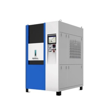
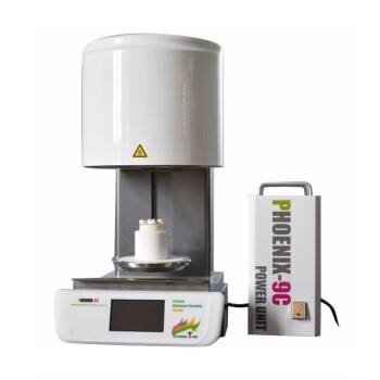
The secret to a high-performance zinc oxide varistor lies not only in its chemical formulation, but in the precise thermal journey it endures inside a high-temperature laboratory furnace. Phase diagram characteristics—particularly the eutectic temperature, the boundaries of the liquid-plus-solid phase field, and the off-eutectic composition—directly dictate the furnace profile. They determine the peak sintering temperature, the heating and cooling rates, and the very stability of the part against slumping, all to convert a pressed powder compact into a dense ceramic with controlled grain boundaries and tailored electrical non-linearity.
The core takeaway: Avoid the eutectic point itself. By choosing a composition slightly off the exact eutectic and setting the peak furnace temperature just above the eutectic in the liquid‑plus‑solid (L+S) field, you replace an instantaneous, catastrophic flood of liquid with a gradual, controllable increase in liquid volume. This single principle prevents shape distortion and gives you the thermal handle needed to engineer the final microstructure.
How Phase Diagrams Define the Sintering Window
A binary phase diagram like ZnO–Bi₂O₃ is the blueprint for the liquid-phase sintering cycle. It tells you at exactly what temperature the first liquid appears and how much liquid will exist as you climb in temperature. Applying that knowledge prevents two common disasters: incomplete densification and catastrophic slumping.
The Eutectic Point: The Danger Zone
For the ZnO–Bi₂O₃ system, the eutectic temperature is 740°C. If your powder mixture sits exactly at the eutectic composition, the entire compact can transform into a liquid almost instantaneously when the furnace crosses that threshold. The result is a collapsed, distorted part. Phase diagrams flag this risk explicitly, steering you away from the eutectic composition.
Off-Eutectic Composition: Gradual Liquid Formation
Setting the overall varistor composition slightly off the eutectic point places it within a solid‑plus‑liquid field (L + S₂). As the furnace climbs beyond 740°C, only a small fraction liquefies initially, and the liquid volume grows slowly with further temperature rise. This progressive melting gives you time and thermal headroom for rearrangement, solution‑precipitation, and densification without losing the part’s shape.
Temperature Selection: The Liquid‑Plus‑Solid Field
The ideal peak sintering temperature sits somewhat above the eutectic temperature, deep enough into the L+S region to generate a sufficient liquid volume fraction for rapid densification, yet well below the temperature where the solid skeleton would completely dissolve. For a typical ZnO varistor, this operating window often falls between 900°C and 1100°C, where a Bi₂O₃‑rich liquid coexists with solid ZnO grains and, in more complex formulations, precipitating spinel phases.
From Liquid to Solid: Cooling Rate and Grain Boundary Engineering
Once the furnace has created the desired liquid distribution, phase diagrams also guide the cooling path. The final solid/liquid composition at grain boundaries depends on whether you quench fast or cool slowly, and that directly sets the electrical performance.
Rapid Quenching vs. Controlled Cooling
A rapid quench from the sintering temperature freezes the high‑temperature structure. The Bi₂O₃‑rich liquid film remains as a continuous, wetting layer between ZnO grains. While this yields a dense body, it often results in a low non‑linear coefficient because the continuous liquid film short‑circuits the grain‑boundary potential barriers.
Non‑Wetting Configurations and Electrical Properties
A controlled slow cool, on the other hand, allows the liquid composition to shift as temperature drops. Secondary phases precipitate, and the intergranular film dewets into isolated pockets or crystallized triple points. This non‑wetting configuration is essential for the double Schottky barriers that give ZnO varistors their high α‑value and voltage‑clamping ability. The phase diagram’s liquidus and solidus lines dictate the cooling rates needed to achieve this.
Beyond the Binary: Multi‑Component Reactions and Pinning
Real ZnO varistor systems include antimony, chromium, and other transition metal oxides. Here, phase diagrams become richer and the furnace profile must accommodate additional solid‑state reactions that generate both liquid and pinning phases.
Pyrochlore Decomposition and Spinel Formation
In systems containing Bi₂O₃, Sb₂O₃, and ZnO, a pyrochlore phase (e.g., Bi₃Zn₂Sb₃O₁₄) forms during heating and then decomposes within a specific temperature window—typically 950°C to 1100°C. This decomposition releases a fresh pulse of liquid Bi₂O₃ while simultaneously creating equiaxed spinel particles such as Zn₇Sb₂O₁₂ or ZnCr₂O₄. The furnace thermal profile must hold long enough inside this window to fully trigger the reaction yet not overshoot and lose the pinning effect.
Zener Pinning Through a Liquid Film
The in‑situ spinel particles are micron‑sized—far thicker than the tens‑of‑nanometers‑wide liquid boundary film that coats ZnO grains. They easily bridge the film and act as strong Zener pinning points, inhibiting grain growth. Maintaining a stable, thin liquid film through precise furnace temperature control raises the activation energy for grain growth to over 300–400 kJ/mol, preserving a fine grain size and a high breakdown voltage.
Translating Phase Diagrams into a Furnace Profile
A phase diagram gives the thermodynamic boundary conditions; the actual heating profile must then be engineered to hit those conditions at the right pace.
The Role of Master Sintering Curves
By collecting shrinkage data at several constant heating rates (e.g., 1 to 20 °C/min), you can construct a Master Sintering Curve (MSC). This model predicts density evolution for any arbitrary thermal history, allowing you to design a heating ramp that steadily approaches the L+S field without overshooting, then transitions to a dwell segment that achieves the target density before the cooling stage begins.
Heating Rate and Hold Time
A moderate heating rate ensures the pyrochlore decomposition window is not skipped; a sufficient dwell at the peak temperature allows the liquid to homogenize and spinel pinning particles to position themselves. After the dwell, the cooling rate is set according to the phase diagram’s liquidus slope to produce the desired grain‑boundary phase distribution. Programmable high‑temperature laboratory furnaces make such multi‑stage profiles repeatable.
Navigating the Trade‑offs and Pitfalls
Every choice guided by a phase diagram involves a compromise. Recognizing the limits prevents over‑optimizing one property at the expense of others.
The Pitfall of Precise Eutectic Composition
Choosing a composition exactly at the eutectic promises maximum liquid at a low temperature, but it brings instantaneous, uncontrolled melting. The part slumps, and the furnace run is lost. This is the most basic—and avoidable—mistake in liquid‑phase sintering design.
The Risk of Over‑Heating or Prolonged Soak
Pushing the temperature too far above the eutectic, or holding too long, increases liquid volume excessively. Grain growth can become uncontrollable, spinel particles can coarsen, and Zener pinning weakens. The result is a varistor with a low breakdown voltage and poor non‑linearity.
Cooling Rate Conflicts
A fast cool may trap a continuous grain‑boundary film that ruins the α‑value. An excessively slow cool can promote exaggerated grain growth even after liquid solidifies, or allow unwanted secondary phases to precipitate in a detrimental morphology. The optimum cooling profile is often a compromise between dewetting kinetics and grain‑boundary engineering, dictated by the specific liquidus and solidus lines.
Making the Right Choice for Your Goal
The phase diagram translates your processing goal into a specific set of furnace parameters. Here is how to align your profile with your primary target.
- If your primary focus is maximum density: Select a peak temperature high inside the L+S field to generate a generous liquid volume, then apply a moderate dwell to allow full rearrangement. Ensure the cooling ramp is fast enough to avoid porosity from solidification shrinkage, but not so fast that macro‑cracks form.
- If your primary focus is uniform, fine grain size: Use the pyrochlore decomposition window to nucleate spinel pinning particles, hold at the peak temperature just long enough for liquid distribution, and then cool at a controlled rate that keeps the liquid film thin and activates Zener pinning.
- If your primary focus is a high non‑linear coefficient (α): Pay closest attention to the cooling segment. A slower, controlled cool through the liquidus temperature promotes dewetting and precipitation of isolated grain‑boundary phases, creating the potential barriers essential for strong non‑linearity.
- If your primary focus is process repeatability across batches: Pre‑construct a Master Sintering Curve for your specific powder lot, then program the furnace with a multi‑segment profile that hits the exact time‑temperature points predicted by the MSC. This decouples the process from minor furnace variability.
Every high‑performance ZnO varistor owes its existence to a furnace profile that is not guessed, but read directly from the phase diagram—transforming thermodynamic boundaries into a precise, repeatable thermal path.
Summary Table:
| Processing Goal / Phase Feature | Furnace Profile Strategy | Microstructural Mechanism | Electrical & Physical Benefit |
|---|---|---|---|
| Off-Eutectic Composition | Peak dwell just above eutectic (900–1100°C) | Gradual liquid formation prevents structural collapse | Preserved part geometry & high density |
| Pyrochlore Decomposition | Hold in reaction window (950–1100°C) | In-situ spinel formation causes Zener grain boundary pinning | Fine, uniform grain size & high breakdown voltage |
| Liquidus Slope / Cooling | Controlled, slow cooling rate | Dewetting of liquid film into isolated grain boundaries | Double Schottky barriers & high $\alpha$-value |
| Master Sintering Curve (MSC) | Multi-segment programmable heating | Predictable density evolution mapped to powder kinetics | High batch-to-batch repeatability |
Need precise thermal control to optimize your liquid-phase sintering profiles? KINTEK specializes in high-performance laboratory equipment and consumables, offering a comprehensive range of customizable high-temperature furnaces—including muffle, tube, rotary, vacuum, CVD, atmosphere, dental, and induction melting furnaces. Designed for strict thermal repeatability and complex multi-stage profiling, our equipment helps researchers and ceramic manufacturers achieve ideal microstructures and superior material properties. Contact us today to customize your high-temperature furnace!
Related Products
- 2200 ℃ Tungsten Vacuum Heat Treat and Sintering Furnace
- High Temperature Muffle Oven Furnace for Laboratory Debinding and Pre Sintering
- 2200 ℃ Graphite Vacuum Heat Treat Furnace
- Vacuum Heat Treat Sintering Furnace Molybdenum Wire Vacuum Sintering Furnace
- 1400℃ High Temperature Laboratory Tube Furnace with Alumina Tube
People Also Ask
- How does a tungsten-heated vacuum sintering furnace prepare (TbxY1-x)2O3 ceramics? Achieve 99%+ Density & Purity
- How do compaction pressure and vacuum sintering optimize porous ceramics? Maximize Density & Toughness
- What wear-resistance enhancements are achieved by powder coating? The Role of Vacuum Sintering Furnaces
- What role does a high-temperature vacuum sintering furnace play in the densification of WC-10(Ni, Ni/Co) alloys?
- How does high-temp vacuum sintering influence Y-TZP mechanical properties? Achieve Max Toughness