Your green body shaping method directly defines the thermal debinding and sintering profile your lab furnace must execute. A die-compacted pellet needs a simple, direct ramp to temperature, while an injection-molded gear requires a painstakingly slow, multi-stage debinding cycle to avoid catastrophic cracking. The shaping technique dictates the green density, pore structure, and—most critically—the binder chemistry and volume, which in turn commands the furnace's heating rate, hold stages, atmosphere, and peak temperature.
The central challenge is not just hitting a peak temperature, but managing the journey there. The shaping method imprints a specific "personality" onto the green body—its density distribution, pore network, and volatile content. A successful sintered part is achieved by programming a furnace cycle that is precisely choreographed to manage these unique physical characteristics through thermal expansion, binder burnout, and atomic diffusion, preventing distortion and achieving full density.
The Direct Link: From Shaping Method to Furnace Profile
The manufacturing route you choose to form a component leaves a distinct fingerprint that dictates its thermal processing journey. These characteristics—binder content, particle packing, and density variations—are non-negotiable commands your furnace cycle must obey.
Binder-Driven Thermal Profiles
The most immediate and non-negotiable influence on your furnace cycle is the type and volume of organic binders in the green body. This directly determines the thermal debinding phase required before high-temperature sintering.
A uniaxially pressed disc might contain a few tenths of a percent of a wax lubricant. Its burnout is a brief, low-temperature hold that can often be integrated into the initial heating ramp without a dedicated dwell.
Injection-molded components are the polar opposite. They can contain up to 40% by volume of a complex polymer binder system. A direct, rapid heat-up is impossible. The furnace must execute a precise, multi-step debinding cycle with very slow heating rates (e.g., 0.1–1°C/min) and extended holds at intermediate temperatures to wick the organic constituents out through capillary action without creating internal pressure that causes blistering or cracking.
Atmosphere as a Process Tool
The decomposition products of these binders dictate the furnace atmosphere. A volatile wax from a pressing lubricant can often be swept away in a flowing air environment through oxidative decomposition.
Dense, injection-molded parts with long diffusion paths for binder removal often require a reducing atmosphere like hydrogen or a flowing inert gas with a partial pressure of oxygen. This ensures complete carbon removal from deep within the part body without leaving behind carbonaceous residues that would inhibit final-stage sintering.
The Hidden Physics: Particle Packing and Pore Geometry
Beyond binder chemistry, the shaping method establishes the fundamental particle and pore architecture of the compact. This structure dictates the thermodynamic driving force and diffusion pathways during atomic mass transport, directly controlling the peak temperature and hold time required.
The Power of Packing Homogeneity
The uniformity of particle packing is the single greatest lever for controlling sintering temperature. A green body with homogeneous packing eliminates large, stable pores that are difficult to close.
Colloidal techniques or wet consolidation methods produce ideally packed compacts. Particles settle into a dense, coordinated network with a fine, uniform pore size distribution. This maximizes grain boundary contact area, creating short, efficient diffusion pathways. The result is that full densification can be achieved at furnace temperatures 200°C to 400°C lower than a poorly packed dry-pressed part of the same nominal composition.
Agglomerated powders from simple die-pressing create a bimodal pore size problem. The fine intra-agglomerate pores densify rapidly, while the coarse inter-agglomerate pores remain stable or even grow through Ostwald ripening. Closing these requires pushing the furnace to higher peak temperatures, often above 1700°C, risking excessive grain growth and oversintering.
The Anisotropy of Pressure
The direction of forming pressure translates directly into directional shrinkage in the furnace, a phenomenon called shrinkage anisotropy.
Uniaxial die pressing aligns particles and platy additives perpendicular to the pressing direction and creates elongated, oriented pores along the same axis. During sintering, the driving force to reduce the surface area of these non-spherical pores differs by direction. A disc will shrink significantly more across its thickness than across its diameter, causing warpage if not carefully supported or modeled.
Cold isostatic pressing (CIP) solves this problem at the source. By applying pressure uniformly from all directions, it produces a compact with a more isotropic pore shape and a random, homogeneous stress state. Parts compacted via CIP display minimal shrinkage anisotropy during firing, yielding far superior dimensional fidelity and making it the preferred method for near-net-shape blanks for complex machined ceramics.
Understanding the Trade-offs: The Danger of Density Gradients
Optimizing a furnace cycle with a perfect simulation is dangerous if the model assumes a homogeneous green body. This assumption is the primary source of post-sintering dimensional error, edge rounding, and cracking.
Initial density variations created by the shaping process are amplified during sintering because dense regions shrink less than porous regions. The most critical gradient is often not from the process itself but from the part's interaction with its surroundings.
The friction between a uniaxially pressed part's edges and the die wall creates a severe density gradient from the top to the bottom. During free sintering, this causes the part to deform predictably but destructively. A far more sophisticated thermal profile cannot correct this mechanical defect; the problem must be solved in the forming stage with better lubrication or by switching to isostatic pressing. If you must sinter a part with known density gradients, your only recourse is to model these starting conditions accurately to predict and compensate for the distortion in the final part geometry.
Making the Right Choice for Your Research or Production Goal
The selection of shaping method and the design of the furnace cycle are a single, integrated engineering problem. Your deepest need is to produce a part with specific geometry, properties, and integrity. Here is how to align your process with your objective.
- If your primary focus is producing a few simple, dense test coupons for material property screening: Uniaxial die pressing with minimal binder is the fastest route. Your furnace cycle is simple and direct because the risks of binder burnout and density gradients are manageable. Focus your effort on optimizing peak temperature and hold time to achieve the desired grain size.
- If your primary focus is achieving the highest possible density and strength at the lowest possible sintering temperature: Invest in colloidal or wet-forming techniques to create a perfectly homogeneous green body with fine, uniform pores. The extra effort in powder preparation pays off exponentially in the furnace, where you can achieve near-full density at temperatures several hundred degrees lower, preventing excessive grain growth.
- If your primary focus is manufacturing complex, net-shape parts with a tight dimensional tolerance: Injection molding is your only practical choice for the shape, but it demands complex furnace programming. Your focus must be on designing a slow, multi-stage debinding cycle informed by thermal analysis (TGA/DSC) of your binder system, and on setting the furnace on a non-reactive, flat substrate to prevent warping and distortion.
- If your primary focus is producing a geometrically perfect, large billet with zero shrinkage anisotropy: Cold isostatic pressing, followed by green machining, is the gold standard. The furnace cycle returns to a state of simplicity because the green body’s structure is isotropic. Your key concern shifts from preventing distortion to ensuring uniform temperature distribution for even densification in a large mass.
By understanding that the green body’s architecture is the furnace’s original command, you move from fixing problems with the heating cycle to preventing them at the forming stage, unlocking the full potential of your high-temperature sintering process.
Summary Table:
| Shaping Method | Binder Vol & Complexity | Key Furnace Cycle Requirement | Main Impact on Sintering |
|---|---|---|---|
| Uniaxial Pressing | Low (< 1%) | Simple, direct ramp; basic low-temp dwell | Risks shrinkage anisotropy & density gradients |
| Injection Molding (PIM) | High (up to 40%) | Multi-stage slow ramp (0.1–1°C/min), controlled atmosphere | Demands precise debinding to prevent cracking |
| Colloidal / Wet Forming | Low to Moderate | Requires 200°C–400°C lower peak temperatures | Maximizes packing homogeneity & densification |
| Cold Isostatic Pressing (CIP) | Low | Standard profile; requires uniform heat distribution | Delivers isotropic shrinkage & high dimensional fidelity |
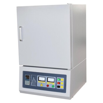
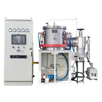
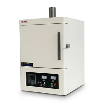
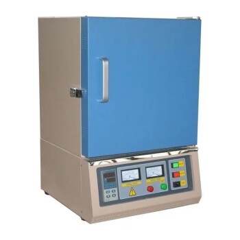
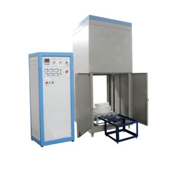
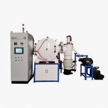
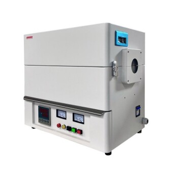
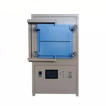
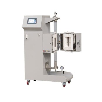
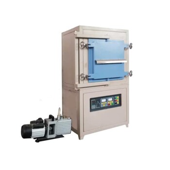
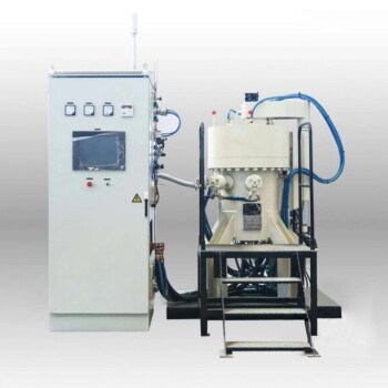
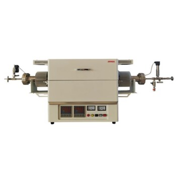
Mastering the interplay between green body shaping and sintering profiles is critical to achieving defect-free, fully dense components. At KINTEK, we specialize in high-performance laboratory equipment and consumables, offering a comprehensive range of customizable high-temperature furnaces—including muffle, tube, rotary, vacuum, CVD, controlled atmosphere, dental, and induction melting furnaces—engineered to meet your precise research and production specs.
Ready to elevate your material processing? Contact KINTEK today to consult with our experts and tailor the ideal furnace system for your laboratory.
Related Products
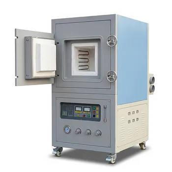
- High Temperature Muffle Oven Furnace for Laboratory Debinding and Pre Sintering
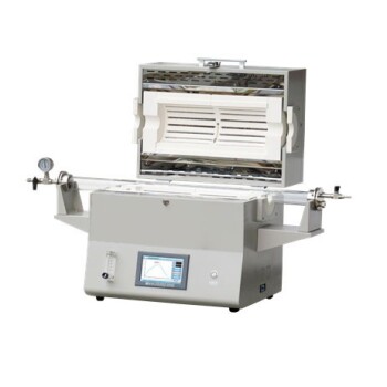
- 1400℃ High Temperature Laboratory Tube Furnace with Alumina Tube
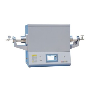
- 1700℃ High Temperature Laboratory Tube Furnace with Alumina Tube
- 1800℃ High Temperature Muffle Oven Furnace for Laboratory
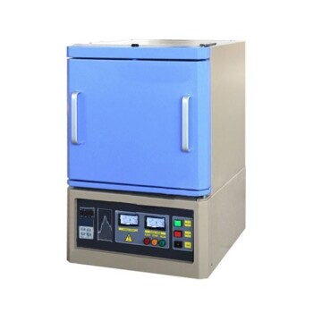
- 1700℃ High Temperature Muffle Oven Furnace for Laboratory
People Also Ask
- What thermal phenomena occur during polymer binder burnout in ceramic green bodies? Lab Furnace Guide
- What role does a high-temperature muffle furnace play in STFO synthesis? Achieve Pure Perovskite Results
- Why is controlled heat treatment in a muffle furnace necessary for calcined clay? Achieve Optimal Pozzolanic Activity
- How does a high-temperature muffle furnace facilitate the formation of LaNbxAl1−xO3+δ perovskite structures? Key Roles
- What role does a high-temperature muffle furnace play in the formation of biochar catalysts? Master Catalyst Synthesis