For a composite with 2D randomly oriented continuous fibers, the effective in-plane Young’s modulus is predicted by the well‑established relation
(E_c = \frac{3}{8} E_f V_f), where (E_f) is the fiber’s elastic modulus and (V_f) is the fiber volume fraction. This simple, theoretical upper‑bound applies when the fibers are much stiffer than the matrix and are perfectly bonded, giving researchers a fast, first‑order prediction of the isotropic in‑plane stiffness of their laboratory‑fabricated samples.
The core takeaway: Classical cell theory reduces a complex, random‑fiber architecture to a single number. For 2D random continuous fibers, the composite modulus is approximately three‑eighths of the fiber modulus times the fiber volume fraction. Use this equation to quickly sanity‑check your experimental results, but remember it assumes the matrix carries negligible load and that no defects are present—conditions rarely met exactly in real furnace‑processed materials.
Why a Simple Formula Matters for Lab‑Synthesized Composites
Laboratory high‑temperature furnaces are used for sintering, pyrolysis, or melt‑infiltration to create fiber‑reinforced ceramics, metals, or polymers.
After hours of thermal processing, you need to know whether your sample achieved its target stiffness—before committing to expensive, time‑consuming mechanical testing.
The closed‑form prediction gives you that immediate feedback.
The Theoretical Foundation: Cell Theory for Planar Random Fibers
When continuous fibers are laid in a truly random in‑plane distribution, the probability density function for fiber orientation is uniform over all angles.
Classical micromechanics then integrates the stiffness contribution of a unidirectional lamina over all planar directions.
For the case where (E_f \gg E_m), the result simplifies dramatically.
Deriving the Key Modulus Components
The in‑plane stiffness tensor of a single, unidirectional ply is rotated and averaged.
Under the assumption that the matrix takes up almost no longitudinal load, cell theory gives the following planar components for the random composite:
- (E_{11} = E_{22} = \frac{3}{8} E_f V_f) (in‑plane normal stiffness)
- (E_{12} = \frac{1}{8} E_f V_f) (in‑plane shear stiffness)
- Poisson’s ratio (\nu_c = 1/3)
This means the material is isotropic in its plane—a property that makes it attractive for thin plates, shells, or coatings where multi‑axial loads are expected.
Clarifying a Common Misstatement
Some summaries incorrectly cite the modulus as (\frac{1}{3} E_f V_f).
That value is actually the Poisson ratio factor, not the Young’s modulus.
The correct, widely documented prediction for the in‑plane tensile modulus is (\frac{3}{8} E_f V_f).
When you encounter the “1/3” factor in older or simplified texts, check whether it refers to Poisson’s ratio rather than modulus—this distinction is critical for accurate material comparison.
How to Apply the Equation in Your Lab
You only need two measured or known values: the fiber’s elastic modulus and the fiber volume fraction in your finished composite.
Measuring Fiber Volume Fraction ((V_f))
The volume fraction is the proportion of the total composite volume occupied by fibers.
Common lab‑friendly methods include:
- Archimedes density method: Measure composite density (\rho_c), matrix density (\rho_m), and fiber density (\rho_f). Solve (\rho_c = \rho_f V_f + \rho_m (1 - V_f)).
- Image analysis: Polish a cross‑section, acquire a high‑contrast micrograph, and use thresholding to count the fiber area fraction (equivalent to (V_f) for continuous fibers).
- Thermogravimetric analysis (TGA): If the matrix can be burned off without damaging the fibers, the residual mass yields (V_f).
Obtaining the Fiber Modulus ((E_f))
Ideally, use the manufacturer’s datasheet value for the fiber after your furnace cycle.
If the thermal treatment itself alters the fiber (e.g., partial crystallization, oxidation), you can extract the modulus from a single‑fiber tensile test or nanoindentation on a fiber cross‑section.
Even a small error in (E_f) propagates linearly to (E_c), so prioritize an accurate value that reflects the post‑process state.
Step‑by‑Step Workflow
- Determine (V_f) using your chosen experimental method.
- Identify or measure (E_f) for the fiber after the thermal cycle.
- Compute (E_c = \frac{3}{8} E_f V_f).
- Optionally, also calculate the shear modulus (G_c = \frac{1}{8} E_f V_f) for applications involving torsion or off‑axis loading.
- Validate the result with a simple tensile or flexural test on a coupon cut from the same furnace batch.
Understanding the Trade-offs
The simplicity of the (\frac{3}{8} E_f V_f) rule is also its greatest limitation.
The “Stiff Fiber” Assumption
The formula is exact only when the matrix stiffness is completely negligible.
In real composites, especially ceramic‑matrix or metal‑matrix systems, the matrix modulus can be 10–30% of (E_f), causing the prediction to underestimate the true modulus.
A more accurate laminate analogy or Mori–Tanaka model can recover the matrix contribution at the cost of added complexity.
Ideal Bonding and No Porosity
The derivation assumes perfect fiber‑matrix bonding and zero voids.
Furnace processing often introduces porosity, microcracks, or debonding due to thermal expansion mismatch.
Each of these defects reduces the measured modulus below the theoretical value, making the formula an upper‑bound reference rather than a guaranteed result.
Truly Random Orientation
Laboratory deposition or hand lay‑up can introduce preferential alignment, even when “random” is intended.
A bias of only a few degrees toward one direction will increase modulus in that direction and reduce it transversely, breaking the planar isotropy.
Quantify orientation distribution via image analysis if you suspect bias; otherwise, treat the (\frac{3}{8}) rule as a baseline for an ideal isotropic scatter.
Making the Right Choice for Your Goal
- If your primary focus is rapid screening of fiber/matrix combinations after furnace cycles: Use (E_c = \frac{3}{8} E_f V_f) as a first pass. It requires minimal data and instantly flags samples that significantly underperform due to poor bonding or high porosity.
- If your primary focus is high‑fidelity prediction for a design‑critical component: Validate the simple prediction with tensile or instrumented indentation tests, then refine the model. Incorporate matrix stiffness through laminate analogy or FEM, and include measured porosity via micromechanical corrections.
- If your primary focus is comparing your lab composite to literature data: Always report the fiber volume fraction and test conditions alongside the measured modulus. State clearly whether the (\frac{3}{8} E_f V_f) line matches your data, so others can assess processing quality quickly.
When you combine a clean measurement of fiber volume fraction and post‑process fiber modulus, the (\frac{3}{8} E_f V_f) rule turns a complex, furnace‑synthesized random‑fiber composite into a trustworthy, instantly calculated property.
Summary Table:
| Parameter | Theoretical Formula / Value | Key Considerations & Methods |
|---|---|---|
| In-Plane Young's Modulus ($E_c$) | $E_c = \frac{3}{8} E_f V_f$ | First-order upper bound assuming $E_f \gg E_m$ and perfect bonding |
| In-Plane Shear Modulus ($G_c$) | $G_c = \frac{1}{8} E_f V_f$ | Useful for off-axis or torsional loading analysis |
| Poisson's Ratio ($\nu_c$) | $1/3$ | Indicates planar isotropic behavior in the composite |
| Fiber Volume Fraction ($V_f$) | Measured experimentally | Evaluated post-furnace via Archimedes method, image analysis, or TGA |
| Fiber Elastic Modulus ($E_f$) | Measured post-process | Post-thermal cycle value extracted from single-fiber tensile or nanoindentation |
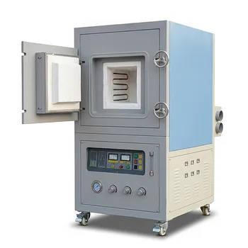
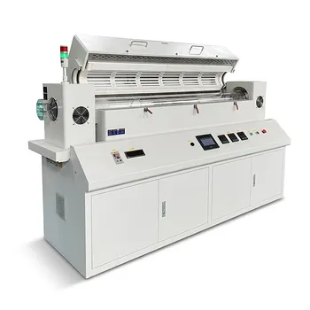
Achieve precise thermal processing for your advanced composite synthesis with KINTEK! We specialize in premium laboratory equipment and consumables, offering a comprehensive range of customizable high-temperature furnaces—including muffle, tube, rotary, vacuum, CVD, atmosphere, dental, and induction melting systems tailored to your research needs. Upgrade your lab capabilities and ensure defect-free material processing—contact us today!
Related Products
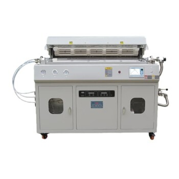
- Multi Heating Zones CVD Tube Furnace Machine for Chemical Vapor Deposition Equipment
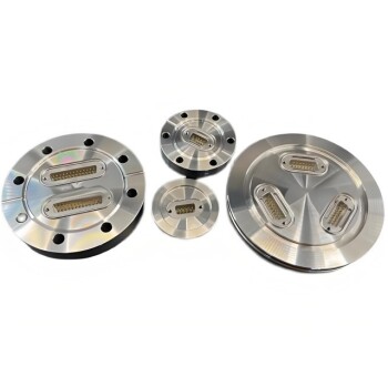
- Ultra-High Vacuum Flange Aviation Plug Glass Sintered Airtight Circular Connector for KF ISO CF
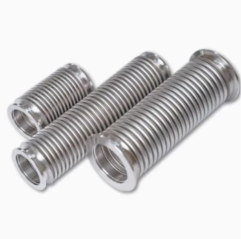
- High Performance Vacuum Bellows for Efficient Connection and Stable Vacuum in Systems
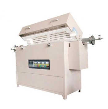
- Multi Zone Laboratory Quartz Tube Furnace Tubular Furnace
- High Temperature Muffle Oven Furnace for Laboratory Debinding and Pre Sintering
People Also Ask
- What is the function of a multi-zone tube furnace in CVD synthesis? Master 2D In2Se3 Nanosheet Precision
- What temperature-related capabilities make multi zone tube furnaces valuable for research? Unlock Precision Thermal Control
- What role do multi zone tube furnaces play in new energy research? Unlock Precise Thermal Control for Innovation
- Why are multi zone tube furnaces particularly useful for nanomaterial research? Unlock Precise Thermal Control for Advanced Synthesis
- What environmental protection applications utilize multi zone tube furnaces? Unlock Precision in Waste Treatment and Green Tech