Three distinct densification stages drive solid-state sintering: an initial neck‑formation phase with barely noticeable shrinkage, an intermediate stage where the compact undergoes nearly all its volume reduction, and a final stage where the last few percent of density are gained from isolated pores. In the first stage, inter‑particle necks grow but dimensional change is limited to 2–3% at most. The intermediate stage delivers the bulk of densification—up to roughly 93% relative density—as interconnected pore channels shrink. The final stage begins when those channels pinch off into isolated spherical pores, and further shrinkage proceeds asymptotically toward the target density.
The key insight: compact shrinkage is not linear. It is negligible during initial neck growth, accelerates dramatically during intermediate channel‑pore collapse, and then slows to a near‑plateau in the final isolated‑pore regime. Understanding this progression lets you tailor furnace ramp rates, hold times, and peak temperatures to lock in high density without trapping pores or triggering runaway grain growth.
The Three Densification Stages and Their Shrinkage Signature
Solid‑state sintering is a continuous thermal process, but researchers and furnace operators partition it into three overlapping microstructural windows because the driving forces and geometric constraints change markedly. Here is how shrinkage maps onto each window.
Stage 1: Initial Neck Formation (Negligible Shrinkage)
When the powder compact first reaches thermal activation temperatures, surface curvature gradients drive material transport to the contacting points between particles. This forms and grows inter‑particle necks.
- The neck‑diameter ratio stays below ~0.3, and the microstructure remains largely unchanged beyond the contact zones.
- Linear shrinkage is limited to 2–3% at most. Relative density rarely exceeds 0.65 during this stage because particles simply weld together without major center‑to‑center approach.
- Surface area stays above 50% of the original powder, and there is essentially no grain growth.
Because shrinkage is so minor, this stage is often used deliberately to burn out binders or hold the part while diffusion mechanisms activate, without prematurely closing pore channels.
Stage 2: Intermediate Pore‑Channel Shrinkage (Major Densification)
Once the neck network is established, mass transport shifts to eliminate the extensive interconnected tubular pore network that runs along grain edges.
- This stage is responsible for the greatest fraction of densification. Relative density climbs from ~0.65 up to roughly 0.93, meaning the compact experiences the overwhelming majority of its linear and volumetric shrinkage.
- Pores remain open and continuous, modeled as cylindrical channels surrounding tetrakaidecahedral grains. As their cross‑section shrinks, the whole body contracts.
- Grain growth begins in the latter half of the stage, and surface area drops significantly. The sintering rate can slow if excessive grain growth reduces the available grain‑boundary area for vacancy annihilation.
From a furnace‑control perspective, the ramp rate and intermediate‑temperature hold are critical here: too fast a ramp can create density gradients, while a well‑timed hold allows the channel network to collapse uniformly.
Stage 3: Final Isolated‑Pore Elimination (Asymptotic Shrinkage)
The transition to the final stage occurs when interconnected pore channels become unstable and pinch off into isolated spherical pores at multi‑grain corners—typically above 92–93% relative density.
- Shrinkage continues, but at a decelerating rate. The remaining 7–8% of densification must be achieved by shrinking isolated pores, a process governed by bulk or grain‑boundary diffusion of vacancies to distant sinks.
- The driving force—the pore’s internal capillary pressure—remains, but diffusion distances increase and pore‑grain junction mobility can be limited.
- Grain growth accelerates because pores no longer pin boundaries as effectively. If grain growth outpaces pore shrinkage, pores can become trapped inside grains, creating residual porosity that is nearly impossible to eliminate.
Precise control of peak temperature and a short final hold are crucial: you want enough time for pore closure but not so much that exaggerated grain growth traps them.
Understanding the Trade‑offs in Furnace Profile Design
Optimizing a heating cycle for full densification is a balancing act between shrinkage rate, pore mobility, and grain coarsening.
- Heating rate vs. density uniformity: A rapid ramp can complete the intermediate stage quickly, but it risks temperature gradients that cause differential shrinkage—leading to warping or internal cracking. A slower ramp gives time for thermal equilibrium but may promote grain growth before pore closure.
- Hold temperature vs. grain growth: A high peak temperature accelerates diffusion and pore elimination, yet it also speeds grain‑boundary migration. The final stage is especially sensitive; a hold that is just a few degrees too high or too long can drive exaggerated grain growth and permanently trap pores.
- Atmosphere management: In reducing or vacuum atmospheres, pore‑gas pressure can oppose capillary forces, slowing shrinkage in the final stage. The furnace atmosphere must be controlled to avoid blistering or incomplete densification as pores approach closure.
The key is recognizing that each stage’s shrinkage behavior dictates the lever you pull: gentle ramps during neck formation, a well‑timed soak during the intermediate densification burst, and restrained heat in the final stage.
How to Apply This to Your Sintering Cycle
The right furnace profile depends on which densification priority matters most for your material and part geometry.
- If your primary focus is avoiding density gradients and cracking: Use a slow ramp through the intermediate stage and ensure thermal uniformity across the load. This trades time for uniform channel‑pore collapse.
- If your primary focus is maximum final density with fine grain size: Ramp quickly through the intermediate stage to limit grain growth, then tightly control the peak temperature and minimize the final hold time so pores close before grains coarsen excessively.
- If your primary focus is binder burnout before pore closure: Hold the compact in the initial stage (where pores are still fully open) at a temperature that cleanly removes binder without trapping decomposition products. Only then proceed to the major densification ramp.
- If your primary focus is cost‑effective throughput: Incrementally optimize the hold times. Since the final stage offers diminishing returns—the last 2–3% of density can require substantially longer holds—evaluate whether a slightly lower density is acceptable for your application.
By aligning your furnace dwell temperatures, ramp rates, and atmosphere settings with the distinct shrinkage character of each sintering stage, you turn a thermal schedule into a precision tool for achieving defect‑free, near‑theoretical‑density components.
Summary Table:
| Stage | Relative Density | Linear Shrinkage | Microstructural Characteristic | Recommended Furnace Control Strategy |
|---|---|---|---|---|
| Stage 1: Initial | Up to ~0.65 | Negligible (2–3%) | Inter-particle neck formation; open pore network | Gentle ramp or thermal soak for binder burnout without pore closure |
| Stage 2: Intermediate | ~0.65 to ~0.93 | Major / Rapid | Collapse of continuous tubular pore channels | Controlled ramp rate and intermediate hold to ensure uniform densification |
| Stage 3: Final | ~0.93 to >0.98 | Asymptotic / Slow | Isolated spherical pores; accelerated grain growth | Precise peak temperature and brief hold to prevent trapped porosity |
Achieve theoretical density and eliminate residual porosity in your sintering process with KINTEK! As a leading specialist in laboratory equipment and consumables, KINTEK offers a comprehensive line of customizable high-temperature furnaces—including muffle, tube, rotary, vacuum, CVD, atmosphere, dental, and induction melting furnaces—engineered for precise thermal control and superior temperature uniformity. Whether you need to fine-tune ramp rates or optimize atmosphere controls, our experts are here to elevate your material research. Contact KINTEK today to customize your high-temperature furnace solutions!
Related Products
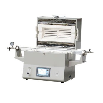
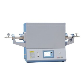
- 1400℃ High Temperature Laboratory Tube Furnace with Alumina Tube
- 1700℃ High Temperature Laboratory Tube Furnace with Alumina Tube
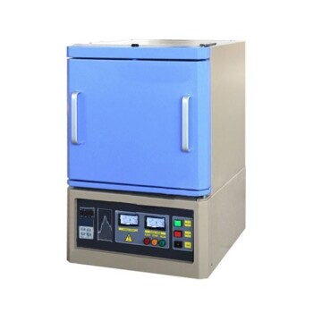
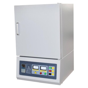
- 1800℃ High Temperature Muffle Oven Furnace for Laboratory
- 1700℃ High Temperature Muffle Oven Furnace for Laboratory
- 1200℃ Muffle Oven Furnace for Laboratory
People Also Ask
- How does zone-melting in tube furnaces synthesize bismuth micro-wires? Master Single-Crystal Thermoelectric Growth
- How are high-temperature laboratory tube furnaces applied in long-term vacuum homogenization heat treatments for intermetallic samples?
- How are high-temp tube furnaces used to measure diffusion coefficients per Fick's law? Master Precision Annealing
- How do high-temperature laboratory tube furnaces ensure environmental stability? Precision Thermal Reduction Tips
- How are high-temperature tube furnaces applied in testing ceramic-supported alloy membranes? Insights