A wetting angle above 90° is a direct predictor of tensile strength collapse in liquid-phase sintered components. When entrapped gas bubbles exhibit a contact angle greater than 90° relative to the solid grains, the liquid phase fails to wet the pore surface. The resulting pore adopts a non-spherical, sharp-edged shape that pinches grain boundaries, drastically reducing the effective load-bearing area and acting as a severe stress concentrator. This morphological penalty immediately translates into lower tensile strength. A wetting angle below 90°, by contrast, allows the molten phase to spread along the grain-pore interface, forcing the bubble into a more rounded, isolated geometry that minimizes mechanical damage.
The core insight: the wetting angle of entrapped gas bubbles does not influence tensile strength through chemistry—it does so entirely through pore shape. Above 90°, pores become strength‑critical stress raisers that split grain boundaries; below 90°, they remain benign, rounded voids. Harnessing the precise thermal and atmospheric control of high‑temperature atmosphere furnaces allows you to push the wetting angle into the safe, sub‑90° regime and eliminate the harmful pore geometries that ruin tensile performance.
The Physics of Pore Morphology and Wetting Angle
How the Contact Angle Governs Pore Shape
The behavior of a gas bubble entrapped between liquid and solid is governed by the same force balance that controls liquid spreading: Young’s equation, (\gamma_{SV} = \gamma_{SL} + \gamma_{LV} \cos(\theta)). Here, the solid is the grain surface, the liquid is the molten sintering phase, and the vapor is the entrapped gas. The contact angle (\theta) describes how the gas–liquid interface meets the solid.
When (\theta > 90^\circ), the liquid does not wet the grain inside the pore. The system minimizes its energy by curling the gas–liquid meniscus away from the grain. This forces the pore to take on a shape that intrudes deeply along grain boundaries, creating sharp cusps and thin, crack‑like voids that wedge the grains apart.
With (\theta < 90^\circ), wetting is favorable. The liquid spreads along the solid‑vapor interface, rounding out the pore. Capillary pressure then collapses the cavity into a near‑spherical, isolated void that sits harmlessly at triple junctions rather than breaching the grain‑to‑grain contacts.
How Pore Shape Determines Stress Concentration and Tensile Strength
Tensile failure in brittle sintered bodies almost always starts at the largest stress concentrator. A pore that pinches a grain boundary acts exactly like a sharp notch. The crack‑tip radius is on the order of the grain‑boundary thickness, so the local stress skyrockets under an external tensile load. The effective load‑bearing area is also diminished because the void replaces a substantial fraction of the grain‑boundary cross section.
In contrast, an isolated spherical pore generated by good wetting ((\theta < 90^\circ)) distributes stress more evenly around its surface. The stress concentration factor for a sphere in a ceramic matrix is around 2, while for a sharp grain‑boundary slit it can exceed 10. That order‑of‑magnitude difference directly dictates whether a component fails at a fraction of its theoretical strength or approaches the intrinsic strength of the dense material.
The Furnace’s Role in Engineering the Wetting Angle
Temperature’s Effect on Interfacial Energies
All three interfacial energies in Young’s equation—(\gamma_{SV}), (\gamma_{SL}), and (\gamma_{LV})—are functions of temperature. Typically, increasing temperature reduces the solid–liquid interfacial energy (\gamma_{SL}) more steeply than the other terms, progressively shrinking the contact angle. A high‑temperature atmosphere furnace lets you precisely target the temperature window where (\gamma_{SL}) drops low enough to drive (\theta) below 90° for a given powder‑binder system. Holding within that window then ensures that any residual gas bubbles adopt the benign, rounded morphology before final pore closure.
Atmosphere Control to Eliminate and Reshape Gas Bubbles
Gas entrapment is often unavoidable, but the atmosphere composition can chemically alter the bubbles. For example, a reducing hydrogen atmosphere can diffuse into a trapped oxygen‑containing bubble and react to form water vapor that subsequently dissolves into the molten glass phase. A vacuum can physically evacuate gas before liquid seals the surface pores. In both scenarios, the furnace atmosphere lowers the volume and pressure of trapped gas, making it easier for capillary forces applied by a well‑wetting liquid to collapse the bubble completely. Even if a bubble remains, the same controlled atmosphere can adjust the melt chemistry to lower (\gamma_{SL}) and thereby push (\theta) below the critical 90° threshold.
Understanding the Trade‑offs
The Dihedral Angle Risk: When Low Wetting Angle Causes Slumping
While a low wetting angle ((\theta < 90^\circ)) is beneficial for pore morphology, it must be balanced against the dihedral angle (\phi), which describes how the liquid sits between two solid grains. The relationship (\gamma_{SS} = 2 \gamma_{SL} \cos(\phi/2)) shows that if (\phi) approaches zero, the liquid penetrates all grain boundaries, completely eliminating solid‑solid contacts. This destroys the rigid skeleton and causes the part to slump or distort during sintering. An overly aggressive push for a low contact angle can therefore trigger shape collapse even as it solves the pore‑shape problem.
Atmosphere–Material Interactions That Can Backfire
Changing the atmosphere to improve wetting can inadvertently alter the melt chemistry. For example, a reducing atmosphere might reduce surface oxides that were beneficial to bonding, or it might introduce carbon contamination from furnace elements. These side effects can raise (\gamma_{SL}) instead of lowering it, moving the contact angle in the wrong direction. The same thermal cycle that benefits one pore population may also accelerate grain growth, trapping new bubbles. Blindly increasing temperature or switching atmospheres without tracking the evolving interfacial energies can degrade tensile strength even while densification appears to improve.
Making the Wetting Angle Work for Your Tensile Strength
Tailoring the wetting behavior of entrapped gas bubbles is rarely a one‑knob problem. Your approach must match your specific densification and mechanical goals.
- If your primary focus is maximizing tensile strength: Use the furnace profile to maintain a sub‑90° wetting angle throughout pore closure by holding at a temperature that minimizes the solid–liquid interfacial energy. This ensures any trapped bubbles round out and stop pinching grain boundaries.
- If your primary focus is achieving full density without dimensional distortion: Constrain the dihedral angle above 10° while keeping (\theta < 90^\circ). This can be done through small additions of grain‑boundary‑segregating dopants that raise (\gamma_{SS}) without harming wetting, all while using the furnace’s precise atmosphere to manage melt composition.
- If your primary focus is processing ceramic–metal composites (cermets) or systems with unavoidable gas entrapment: Pair a favorable wetting angle with an atmophere‑assisted degassing step—for instance, a low‑temperature vacuum hold before liquid formation, or a hydrogen soak to chemically dissolve the entrapped gas. Reducing the bubble volume magnifies the morphological benefit of a low (\theta).
Manipulating the wetting angle of a trapped gas bubble is not about chasing a single number—it is about mastering the interplay between pore geometry, capillary stress, and furnace conditions to convert a strength‑robbing defect into a manageable microstructural feature. With the thermal and atmospheric precision of a high‑temperature atmosphere furnace, that conversion becomes a repeatable engineering decision rather than a gamble.
Summary Table:
| Process Parameter / Metric | Non-Wetting Regime (θ > 90°) | Wetting Regime (θ < 90°) |
|---|---|---|
| Pore Morphology | Sharp-edged, crack-like, non-spherical cusps | Rounded, isolated near-spherical voids |
| Location relative to Grains | Intruding along grain boundaries | Positioned benignly at triple junctions |
| Stress Concentration Factor | Severe (> 10) | Low (~ 2) |
| Impact on Tensile Strength | Direct strength collapse & premature failure | Preserves high intrinsic material strength |
| Furnace Control Mechanism | Suboptimal temperature / non-reactive gas | Targeted high temperature & tailored reducing/vacuum atmosphere |
Ready to eliminate strength-robbing defects and achieve precise microstructural control in your sintered components? KINTEK specializes in high-performance laboratory equipment and consumables, offering a comprehensive range of customizable high-temperature furnaces—including atmosphere, vacuum, CVD, tube, muffle, and induction melting systems. Whether you are engineering complex cermets or optimizing advanced ceramics, our solutions deliver the exact thermal and atmospheric precision you need. Contact us today to consult with our high-temperature furnace experts!
Related Products
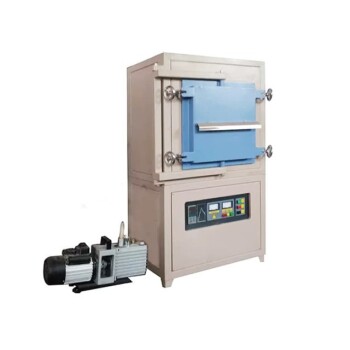
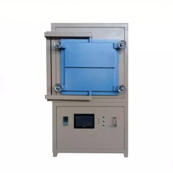
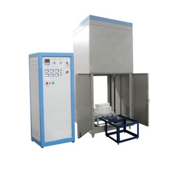
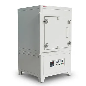
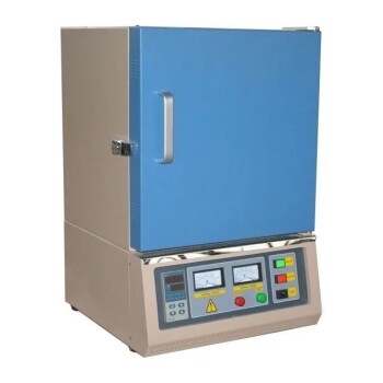
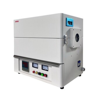
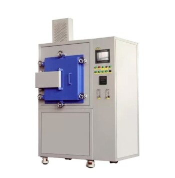
- 1700℃ Controlled Inert Nitrogen Atmosphere Furnace
- 1400℃ Controlled Inert Nitrogen Atmosphere Furnace
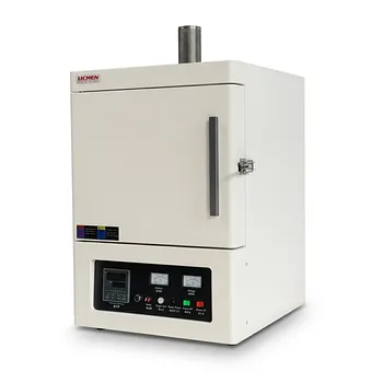
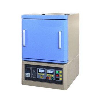
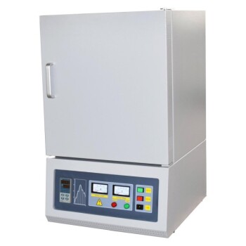
- 1200℃ Muffle Oven Furnace for Laboratory
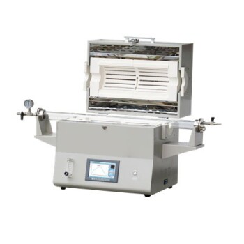
- 1400℃ High Temperature Laboratory Tube Furnace with Alumina Tube
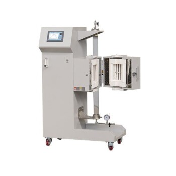
- Laboratory Muffle Oven Furnace with Bottom Lifting
People Also Ask
- How does real-time dilatometric analysis in a controlled-atmosphere furnace optimize PZT ceramic sintering?
- How does oxygen partial pressure control affect ceramic sintering? Master Defect Chemistry
- Why is thorough binder burnout necessary before sintering advanced ceramics? Ensure Peak Density & Zero Defects
- How do controlled-atmosphere furnaces support polymer pyrolysis? Master SiC & Si3N4 Ceramic Conversion
- Why is controlled-atmosphere heating required for functional ceramics and sensors? Master Defect Engineering