The Composite Sphere Model maps the microscopic stress state of a particulate composite during high-temperature sintering by treating it as an array of idealized composite spheres. Each sphere has a rigid inclusion core surrounded by a cladding of the porous, densifying matrix. As the matrix shrinks around the non-shrinking inclusion during furnace heating, the model calculates the resulting hydrostatic tensile stresses, giving engineers a direct window into the thermal-mechanical conditions that lead to cracking or debonding.
The Composite Sphere Model uses a simple geometric idealization to predict transient stresses and densification behavior, allowing you to pinpoint the exact heating rates, hold times, and pressures that prevent microstructural defects during furnace sintering.
Understanding the Composite Sphere Model
The Core-Cladding Representative Element
The model represents the entire composite as a periodic array of identical composite spheres.
Each sphere is a representative volume element with two distinct zones: a rigid inclusion core and a concentric cladding of porous matrix.
This geometric simplification works because the inclusion size is significantly larger than the matrix particles, making the matrix appear as a continuous, densifying medium around each core.
Modeling Porous Matrix Shrinkage
The matrix cladding is not treated as a discrete powder but as a continuum with phenomenological constitutive equations.
These equations capture the relationship between sintering stress, creep, and density evolution during heating.
By applying porous material mechanics to the cladding, the model can predict how the matrix volume changes as it densifies, and how that shrinkage interacts with the rigid core.
How the Model Reveals Transient Stresses
Differential Shrinkage and Tensile Stress Generation
During furnace heating, the matrix attempts to densify by shrinking onto the non-shrinking inclusion.
This constrained shrinkage creates differential strain between the core and the cladding, which the model translates directly into hydrostatic tensile stresses around the inclusion.
These stresses are transient—they build up as the matrix sinters and relax only if hold times are long enough for creep to accommodate the mismatch.
Predicting Densification Behavior During Heating
The model doesn’t just output stress; it also forecasts the overall densification rate of the composite.
As the matrix cladding densifies and transmits stress to the inclusion, the local hydrostatic stress state alters the matrix’s own sintering potential.
This coupling allows researchers to simulate how a full thermal cycle influences the final part density and whether stress concentrations will halt densification prematurely.
Translating Model Insights to Furnace Parameters
Avoiding Stress-Induced Defects with Thermal Holds
The model’s stress predictions directly inform optimal thermal hold times.
By calculating how fast tensile stress decays via creep at a given temperature, you can design hold plateaus that drop stress below the material’s cohesion limit before cooling.
This prevents radial cracks or inclusion-matrix debonding that standard trial-and-error cycles often miss.
Pressure-Assisted Sintering and Contact Stress Amplification
When external pressure is applied during high-temperature furnace processing, the model’s value extends to pressure-assisted sintering (hot pressing).
In the early stages of densification, pressure concentrates at microscopic particle contacts, creating effective contact stresses up to ten times the applied pressure.
This contact stress amplification drives rapid plastic flow and rearrangement. The Composite Sphere Model incorporates these mechanics by adjusting the matrix cladding’s constitutive response, letting you calibrate initial load schedules to maximize densification without causing die failure or grain coarsening.
Validating Stress Predictions via Loading Dilatometry
The model’s outputs are validated using loading dilatometry, where a small uniaxial load is applied to a powder compact in a high-temperature furnace.
By measuring both axial ($\dot{\varepsilon}_z$) and radial ($\dot{\varepsilon}_r$) strain rates, researchers mathematically decouple densification strain from creep strain.
This gives precise values for densification viscosity ($\eta_p$), creep viscosity ($\eta_c$), and equivalent sintering stress ($\Sigma$) —the exact parameters the Composite Sphere Model needs to produce accurate stress maps.
Understanding the Trade-offs
When the Continuum Assumption Breaks Down
The model’s accuracy hinges on the inclusion size being much larger than the matrix particle size.
If the matrix particles are comparable in scale to the inclusions, the continuum cladding assumption fails, and discrete particle interactions dominate.
The phenomenological constitutive equations also smooth over granular effects like inter-particle friction and local density variations, which can lead to under-prediction of stress concentrations in very early stage sintering.
Sensitivity to Inclusion Arrangement and Volume Fraction
The model assumes a uniform array of identical composite spheres, ignoring effects like inclusion clustering or size distributions.
In real composites, local variations in inclusion spacing can create stress hotspots that the idealized model misses.
The volume fraction of inclusions also directly changes the hydrostatic stress magnitude; the model works best at moderate to low inclusion contents where sphere-sphere interactions remain negligible.
Making the Right Choice for Your Process
To apply the Composite Sphere Model effectively, align your modeling scope with your real-world furnace constraints.
- If your primary focus is avoiding micro-cracking during sintering: Use the model to identify the critical heating rate and a thermal hold window that allows tensile stresses to relax through creep before the matrix becomes brittle.
- If your primary focus is optimizing pressure-assisted cycles: Integrate model-derived contact stress amplification with loading dilatometry data to set initial hydraulic pressures that exploit rapid particle flow without exceeding the die’s yield strength.
- If your primary focus is translating lab measurements to production: Calibrate the model’s viscosity and sintering stress parameters from loading dilatometry tests, then scale the predictions to full furnace runs by accounting for part geometry and heating uniformity.
- If your primary focus is selecting compatible inclusion-matrix pairs: Simulate the transient stress evolution for candidate materials; the model will reveal whether differential shrinkage creates stresses that exceed the interface bond strength at any point in the cycle.
The Composite Sphere Model turns the hidden thermal-mechanical history of your furnace into a clear, predictive map—use it to move from reactive defect fixing to proactive cycle design.
Summary Table:
| Modeling Aspect | Core Mechanism | Sintering Process Impact |
|---|---|---|
| Core-Cladding RVE | Idealizes rigid core inside densifying porous matrix | Maps hydrostatic tensile stresses to prevent micro-cracking |
| Differential Shrinkage | Matrix contracts around non-shrinking inclusion core | Defines thermal hold plateaus required for stress relaxation via creep |
| Contact Stress Amplification | Concentrates external pressure at microscopic particle contacts | Optimizes initial load schedules in pressure-assisted sintering |
| Loading Dilatometry Validation | Decouples axial and radial strains under uniaxial load | Calibrates viscosity ($\eta_p, \eta_c$) and sintering stress ($\Sigma$) parameters |
Achieve precise thermal control and defect-free densification in your composite sintering processes with KINTEK. As experts in laboratory equipment and consumables, KINTEK offers a comprehensive line of fully customizable high-temperature furnaces—including muffle, tube, vacuum, atmosphere, CVD, and induction melting systems—designed to satisfy stringent thermal processing demands. Contact KINTEK today to optimize your furnace parameters and partner with our high-temp processing specialists!
Related Products
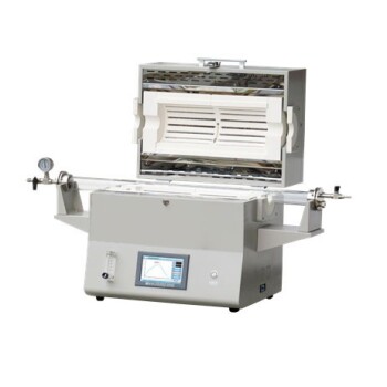
- 1400℃ High Temperature Laboratory Tube Furnace with Alumina Tube
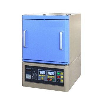
- 1800℃ High Temperature Muffle Oven Furnace for Laboratory
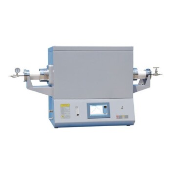
- 1700℃ High Temperature Laboratory Tube Furnace with Alumina Tube
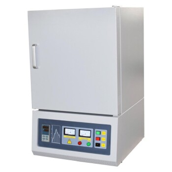
- 1700℃ High Temperature Muffle Oven Furnace for Laboratory
- 1700℃ Controlled Inert Nitrogen Atmosphere Furnace
People Also Ask
- How does zone-melting in tube furnaces synthesize bismuth micro-wires? Master Single-Crystal Thermoelectric Growth
- How are high-temp tube furnaces used to measure diffusion coefficients per Fick's law? Master Precision Annealing
- How do high-temperature laboratory tube furnaces ensure environmental stability? Precision Thermal Reduction Tips
- How are high-temperature laboratory tube furnaces applied in long-term vacuum homogenization heat treatments for intermetallic samples?
- How are high-temperature tube furnaces applied in testing ceramic-supported alloy membranes? Insights