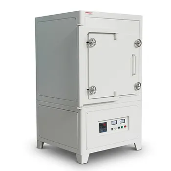
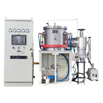
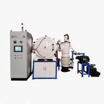
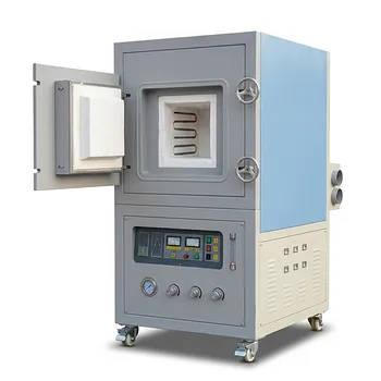
The accurate control of low oxygen partial pressure in high-temperature atmosphere furnaces relies on thermodynamic equilibrium gas mixtures. For pressures as low as 10⁻¹² atm, simple inert gas purging fails due to residual oxygen impurities. Instead, precisely proportioned reactive gas blends—typically H₂–H₂O or CO–CO₂—are flowed through the furnace chamber under constant, monitored conditions. To produce a known water vapor pressure, H₂ gas is bubbled through distilled water held at a tightly controlled temperature (e.g., 11.1 °C), and the equilibrium reaction H₂ + ½O₂ ⇌ H₂O then sets a stable, calculable pO₂ at the sintering temperature. Simultaneous safety measures are non-negotiable: leak‑tight delivery circuits, continuous flow monitoring, dedicated exhaust venting, and explosion‑proof protocols for H₂ and toxicity‑handling for CO must be implemented throughout the entire process.
Low‑oxygen atmospheres are not just about preventing oxidation; they are a fundamental tool to manipulate point defect chemistry, accelerate densification, and avoid volatile‑phase formation in oxide ceramics. The core method is to establish a thermodynamically defined pO₂ using equilibrated gas mixtures, while the top safety priority is to rigidly control the reactive and toxic gas streams to protect both personnel and equipment.
Why Low Oxygen Pressure Is Non-Negotiable in Ceramic Sintering
The surface question of “how” is only meaningful when we understand “why” controlling pO₂ matters. In oxide ceramics, the gas atmosphere directly writes the material’s defect story—and the defect story determines whether the material densifies, coarsens, or deteriorates.
Defect Chemistry Governs Mass Transport
Ionic ceramics densify primarily through vacancy‑mediated diffusion. The atomic self‑diffusion coefficient Dₐ scales directly with the vacancy concentration Cᵥ.
In non‑stoichiometric oxides—think NiO, CoO, TiO₂, or FeO—Cᵥ is not a fixed property; it follows a power‑law dependence on the ambient oxygen partial pressure.
Under reducing conditions (low pO₂), lattice oxygen leaves the crystal, creating oxygen vacancies and free electrons.
This raises the concentration of the slowest‑moving ionic species, often the rate‑limiting ion, and dramatically accelerates sintering kinetics.
Conversely, an oxidizing atmosphere consumes oxygen vacancies, creating electron holes or metal‑site vacancies, which can slow densification or alter final stoichiometry.
The Cr₂O₃ Cautionary Tale
Chromium‑oxide‑based ceramics illustrate a vivid risk. At high temperatures (1600–1740 °C), if the pO₂ rises above about 10⁻¹⁰ atm, chromium forms volatile CrO₂ or CrO₃.
Vapor‑phase transport then creates neck growth and coarsening without the volume shrinkage that leads to densification.
By holding pO₂ tightly around 10⁻¹² atm, Cr is stabilized in its trivalent Cr³⁺ state, and relative densities exceeding 99 % become achievable.
Control of pO₂ is therefore not an option—it is a prerequisite for reaching near‑theoretical density in such systems.
Tuning Functional Properties Directly
For oxides with variable‑valence cations, the sintered stoichiometry and the resulting electrical or optical performance are set by the furnace atmosphere.
A higher pO₂ during cooling can freeze‑in metal vacancies for enhanced conductivity; a lower pO₂ in the soak can tailor optical absorption edges.
Thus, the ability to precisely manipulate pO₂ transforms the sintering process from a simple densification step into a functional‑property design tool.
How Ultra-Low pO₂ Is Achieved with Gas Mixtures
Achieving pO₂ below about 10⁻⁴ atm requires moving beyond inert‑gas flushing. The core strategy is to introduce a thermodynamic buffer that pins the oxygen activity through a reversible chemical equilibrium.
The H₂–H₂O Buffer: Precision Through Temperature‑Controlled Humidification
Hydrogen gas is passed through a water bubbler held at a precise temperature.
For instance, maintaining the water at 11.1 °C sets a saturated H₂O vapor pressure of exactly 0.013 atm.
This moist H₂ stream enters the furnace, where the reaction
H₂ + ½O₂ ⇌ H₂O
quickly establishes equilibrium at the processing temperature. At 1600 °C, the resulting pO₂ is a stable 10⁻¹¹·⁷ atm.
By changing the bubbler temperature, the H₂O/H₂ ratio shifts, giving fine control over the equilibrium oxygen partial pressure over several orders of magnitude.
The CO–CO₂ System: Mixing for Thermodynamic Set‑Points
An alternative route uses carbon monoxide – carbon dioxide mixtures.
Gases are combined in fixed proportions—often by passing them through a column packed with glass beads to ensure thorough blending—before entering the hot zone.
The equilibrium CO + ½O₂ ⇌ CO₂ then defines the pO₂.
Though less common than H₂–H₂O for ultra‑low pO₂ because of CO’s toxicity and carbon‑deposition risks at lower temperatures, this method is highly effective and can be calibrated to cover a wide range of oxygen activities.
Why Inert‑Gas Purging Alone Is Insufficient
Even “high purity” argon or nitrogen contains 10–100 ppm of oxygen.
At high temperature, this residual impurity can produce an oxygen partial pressure far above the desired ultra‑low level.
The reactive equilibrium mixtures act as a self‑correcting buffer: any excess oxygen immediately shifts the equilibrium, regenerating the low pO₂ set‑point, which a simple flow of inert gas cannot do.
Essential Safety Measures for Reactive Atmosphere Furnaces
H₂ is explosive, CO is toxic, and both systems operate at elevated temperatures. Safety must be designed into the gas delivery, exhaust, and monitoring infrastructure from the start.
Leak‑Tight Gas Delivery and Sealing
Every joint, fitting, and tube in the gas path must be rated for the operating pressure and checked regularly for leaks.
Even small hydrogen leaks in a confined space can generate a combustible mixture. Using metal tubing with welded or high‑integrity compression connections, combined with a rigorous pressure‑decay test at commissioning, is standard practice.
Continuous Flow Monitoring and Interlocks
Mass flow controllers (MFCs) with calibrated ranges for each gas provide real‑time measurement and automated flow adjustment.
If a flow deviates outside the safe window, interlocks should immediately shut off reactive gas supply and purge the system with inert gas.
Combined with hydrogen‑specific sensors in the room and exhaust line, this creates a layered defense.
Safe Exhaust Venting and Atmosphere Management
The furnace exhaust must be ducted to a safe outdoor location, with dilution air if necessary, to prevent accumulation of combustible or toxic gases.
For H₂ atmospheres, the vent line often includes a flashback arrestor and a flame‑arrestor device.
Before opening the furnace at temperature, a thorough purge with an inert gas must be completed to eliminate any remaining reactive mixture.
CO‑Specific Precautions
Because CO is odorless and highly toxic, CO systems require dedicated gas detectors in the operator area and strict protocols for cylinder storage and line purging.
Personnel must be trained in gas safety and equipped with personal monitors when working near the furnace.
Understanding the Trade‑offs and Practical Limits
No single atmosphere system is universally superior. The choice between H₂–H₂O and CO–CO₂ involves balancing control precision, safety, material compatibility, and practical laboratory constraints.
Material Compatibility
H₂ is a potent reducing agent that can over‑reduce certain oxides at very low pO₂, leading to metallic precipitates.
In such cases, a CO–CO₂ mixture may provide a milder reducing environment with less risk of undesirable reduction.
Conversely, carbon monoxide can carburize some ceramics or promote carbon deposition at lower temperatures if the gas composition is not carefully maintained above the Boudouard equilibrium.
Operational Complexity and Cost
H₂–H₂O systems require a well‑controlled bubbler and, ideally, a hygrometer to verify the incoming humidity.
The water temperature must be stable to within ±0.1 °C to maintain precise pO₂ values.
CO–CO₂ setups demand rigorous fume hoods, gas monitors, and often more complex blending hardware.
Both systems require experienced personnel and regular maintenance, making them more expensive than simple inert‑gas furnaces.
Reproducibility and Monitoring Pitfalls
True pO₂ inside the hot zone can deviate from the calculated equilibrium if there are temperature gradients, gas‑flow dead zones, or leaks.
Installing an in‑situ oxygen sensor (e.g., a zirconia probe) is the most direct method to verify the actual pO₂, but such sensors may not survive the most extreme reducing conditions or temperatures.
Reliance on theoretical calculations alone can lead to process drift; periodic validation with witness samples is the prudent approach.
Making the Right Choice for Your Sintering Goal
The ideal configuration depends on the ceramic system you are processing and the property you are targeting. The following action‑oriented recommendations will help you align the atmosphere strategy with your primary objective.
- If your primary focus is densifying non‑stoichiometric oxides (NiO, CoO, TiO₂): Use an H₂–H₂O buffer to dynamically raise oxygen‑vacancy concentration and accelerate vacancy‑diffusion kinetics; verify the pO₂ set‑point with a bubbler temperature that keeps water vapor pressure stable to within 0.1 °C.
- If your primary focus is avoiding volatile oxide formation in Cr₂O₃ or chromite ceramics: Maintain an ultra‑low pO₂ of about 10⁻¹² atm via H₂–H₂O to stabilize Cr³⁺ and achieve >99 % density; include a zirconia oxygen sensor to confirm the actual atmosphere inside the hot zone.
- If your primary focus is a milder reducing environment without hydrogen embrittlement or over‑reduction: Opt for a CO–CO₂ mixture, but implement rigorous CO monitoring, dedicated exhaust extraction, and carbon‑deposition mitigation by keeping the CO/CO₂ ratio above the Boudouard limit.
- If your primary focus is functional property tuning (electrical/optical) through defect engineering: Use either gas system, but match the cooling‑segment atmosphere to the desired final vacancy concentration; document the exact pO₂ history for process repeatability.
- If your primary focus is laboratory safety and compliance: Design the gas delivery with double‑containment piping, automated shut‑off interlocks triggered by flow deviation or gas detection, and a written purge‑before‑open procedure for every cycle.
Equipped with these thermodynamic and safety principles, you can transform the furnace atmosphere from a vague processing variable into a precise tool that dictates defect chemistry, densification, and the ultimate performance of your ceramic component.
Summary Table:
| Gas Buffer / Strategy | Control Mechanism | Typical $pO_2$ Range | Primary Advantage | Major Risk / Safety Protocol |
|---|---|---|---|---|
| $H_2–H_2O$ Buffer | Temperature-controlled water bubbler ($H_2 + \frac{1}{2}O_2 \rightleftharpoons H_2O$) | Down to $10^{-12}$ atm | High precision, ideal for oxide ceramics (e.g., $Cr_2O_3$) | Hydrogen flammability; requires continuous flow sensors & explosion-proof venting |
| $CO–CO_2$ Buffer | Fixed reactive gas mixing ratios ($CO + \frac{1}{2}O_2 \rightleftharpoons CO_2$) | Moderate to ultra-low $pO_2$ | Milder reducing power; avoids over-reduction | High CO toxicity & carbon deposition; demands dedicated gas detectors |
| Inert Gas Purge ($Ar/N_2$) | Dilution / physical displacement of ambient air | Limited to $\sim 10^{-4}$ atm | Low complexity, safe operational setup | Residual impurities permit oxidation; unsuitable for defect engineering |
Take Control of Your Atmosphere Sintering with KINTEK
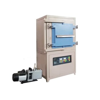
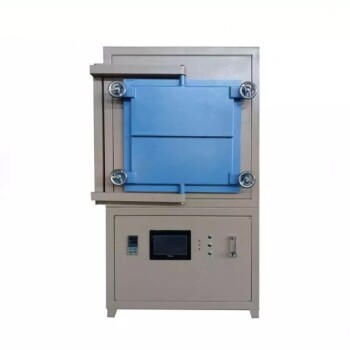
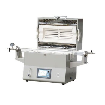
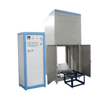
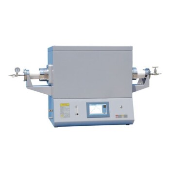
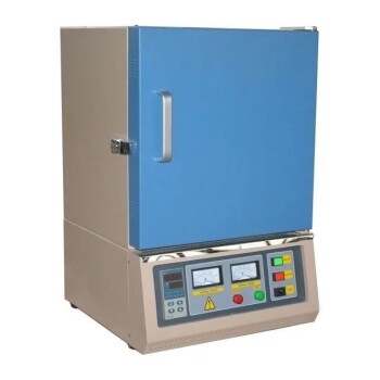
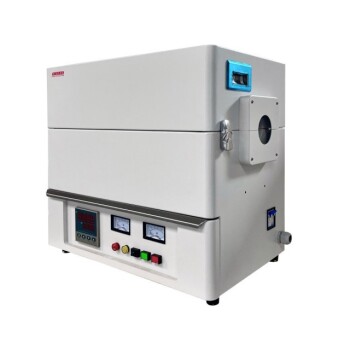
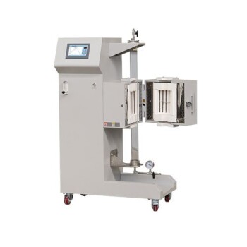
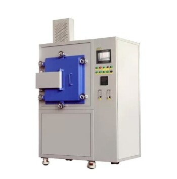
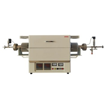
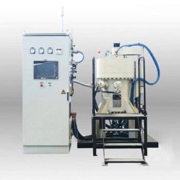
Precise $pO_2$ control and absolute safety shouldn't be a trade-off in your laboratory. At KINTEK, we specialize in high-performance laboratory equipment, offering a comprehensive range of customizable high-temperature atmosphere furnaces, tube furnaces, vacuum furnaces, and CVD systems tailored to your exact thermodynamic and safety requirements.
Whether you are engineering defect chemistry in advanced ceramics or scaling up production, our furnaces come equipped with high-integrity sealing, automated gas-mixing units, and integrated safety interlocks designed for handling $H_2$, $CO$, and inert gas mixtures.
Ready to elevate your ceramic sintering precision?
👉 Contact KINTEK Experts Today to discuss your application or request a customized furnace solution!
Related Products
- 1700℃ Controlled Inert Nitrogen Atmosphere Furnace
- 1400℃ Controlled Inert Nitrogen Atmosphere Furnace
- 1200℃ Muffle Oven Furnace for Laboratory
- 1400℃ High Temperature Laboratory Tube Furnace with Alumina Tube
- Laboratory Muffle Oven Furnace with Bottom Lifting
People Also Ask
- Why is thorough binder burnout necessary before sintering advanced ceramics? Ensure Peak Density & Zero Defects
- How does real-time dilatometric analysis in a controlled-atmosphere furnace optimize PZT ceramic sintering?
- How does oxygen partial pressure control affect ceramic sintering? Master Defect Chemistry
- How do controlled-atmosphere furnaces support polymer pyrolysis? Master SiC & Si3N4 Ceramic Conversion
- Why is controlled-atmosphere heating required for functional ceramics and sensors? Master Defect Engineering