The key to unlocking precise ceramic densification lies in real-time shrinkage data.
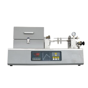
Continuous dilatometry integrates a high-temperature laboratory furnace with a push-rod and Linear Variable Displacement Transducer (LVDT) to track linear shrinkage (ΔL/L₀) through an entire thermal cycle. By recording this dimension change as a function of temperature and time, researchers directly calculate the compact’s relative density and instantaneous densification rate—without running multiple batch experiments. This single dynamic measurement reveals the exact temperature windows where mass transport accelerates, enabling data-driven optimization of furnace heating profiles and hold times.
Sintering kinetics are not a black box. Continuous dilatometry gives you the kinetic fingerprint of a powder compact—onset temperature, shrinkage rate, and apparent activation energy—so you can precisely tune your high-temperature furnace to maximize density while sidestepping grain growth and defects.
How Continuous Dilatometry Captures Sintering Kinetics
The Experimental Setup: Push‑Rod, LVDT, and Controlled Furnace
A ceramic powder compact is placed inside a high-temperature laboratory furnace and a lightweight push‑rod transmits dimensional changes to a high‑resolution LVDT.
The furnace applies a precise heating ramp (e.g., 5–10 °C/min up to 1500 °C) while the data‑acquisition system records ΔL/L₀ continuously. Stable, repeatable ramp rates are essential—any fluctuation distorts the shrinkage‑rate curve and undermines kinetic analysis.
From Linear Shrinkage to Instantaneous Densification Rate
Assuming isotropic shrinkage, the measured linear strain (ΔL/L₀) converts directly to volumetric strain.
The time derivative yields the instantaneous densification rate (dρ/dt), which reveals when densification is fastest and when it stalls.
This real‑time curve pinpoints the onset temperature of sintering with far greater precision than a “cook‑and‑look” approach.
Researchers can then link rate peaks to specific mass‑transport mechanisms and judge the effectiveness of sintering aids or dopant chemistry.
Uncovering Sintering Mechanisms with Atmosphere and Loading Control
Distinguishing Mass Transport Modes via Controlled Atmosphere
By running the same dilatometry experiment under synthetic air, argon, and CO₂, the shrinkage curves can separate surface‑diffusion–dominated stages from those controlled by grain‑boundary or volume diffusion.
For example, if shrinkage accelerates dramatically at low temperatures in air but is suppressed in inert gas, oxidative surface reactions are likely the rate‑limiting step. This insight guides the choice of furnace atmosphere during the critical densification window and helps set gas‑switching intervals for maximum throughput.
Loading Dilatometry: Extracting Sintering Stress and Viscosity
When a small, constant uniaxial load is applied to a cylindrical compact inside an isothermal high‑temperature furnace, the system simultaneously measures axial and radial strain rates.
From those, researchers compute the volumetric densification rate (ε̇_ρ) and the creep strain rate (ε̇_c). The ratio ε̇_ρ/ε̇_c, when analyzed across different applied stresses, directly yields the intrinsic sintering stress (Σ) and densification viscosity (η_ρ)—the fundamental thermodynamic and kinetic parameters that govern the entire sintering trajectory.
Operating inside a high‑temperature atmosphere furnace keeps the partial pressure of oxygen or other gases precisely controlled, preventing unintended oxidation or reduction that would invalidate the extracted material properties.
Transforming Raw Data into Predictive Power
Determining Apparent Activation Energy
Fitting the shrinkage‑rate data from a constant‐heating‐rate run to kinetic models yields the apparent activation energy (Q) for densification.
Because the rate factor follows an Arrhenius dependence, a higher Q means densification is more sluggish at low temperatures but accelerates sharply once thermal energy crosses the barrier. This number is the cornerstone for predicting behavior under any time–temperature profile and for diagnosing whether a dopant truly lowers the activation barrier.
Building a Master Sintering Curve (MSC)
By combining several dilatometry runs at different heating rates, you can construct a Master Sintering Curve (MSC) that collapses all the data onto a single curve linking density to a temperature‑compensated time parameter.
Built on the combined‑stage sintering model, the MSC separates microstructural geometry from temperature‑dependent kinetics. Once validated for a given powder and forming process, this empirical curve predicts the final density for any thermal schedule—enabling rapid optimization of furnace profiles without additional experiments.
Managing the Densification–Coarsening Trade‑Off
High‑temperature dilatometry also exposes the density–grain‑size conflict.
Grain growth follows a kinetic law (G^m = G₀^m + Kt) where the growth factor K scales exponentially with temperature.
Push the furnace too aggressively to reach high density, and grain boundaries migrate so fast that the final microstructure becomes coarse, degrading mechanical properties.
Continuous shrinkage data lets you define the exact time–temperature window where densification is still active but grain growth remains sluggish, so you can design a thermal profile that maximizes density while preserving fine grains.
Common Pitfalls When Interpreting Dilatometric Data
- Push‑rod friction and thermal expansion: Misalignment or drift in the push‑rod assembly can introduce artifacts that look like shrinkage. Always calibrate with a non‑sintering reference sample.
- Anisotropic shrinkage: If a compact densifies unevenly, the simple ΔL/L₀‑to‑density conversion breaks down. In such cases, load‑free dilatometry must be complemented by geometric measurements.
- Atmosphere‑dependent sensor drift: LVDTs can shift at extreme temperatures or in reducing atmospheres; use shielded or high‑temperature–rated transducers and verify baselines.
- Assumption of isothermal conditions: During rapid ramps, the sample may lag the furnace thermocouple reading, leading to temperature errors in the kinetic analysis. Soak segments and slower ramps improve accuracy.
Making the Right Choice for Your Sintering Study
Your goal determines how you deploy continuous dilatometry.
- If your primary focus is identifying the optimal sintering temperature with minimal experiments: Run a single constant‑heating‑rate dilatometry cycle under your production atmosphere. The shrinkage‑rate peak tells you exactly where to set your isothermal hold.
- If your primary focus is predicting density for any future thermal profile: Build a Master Sintering Curve from 3–4 dilatometry runs at different heating rates. Use the MSC to simulate any cycle and lock in your target density in one shot.
- If your primary focus is separating densification from creep and measuring intrinsic sintering stress: Adopt loading dilatometry inside an atmosphere furnace. The ε̇_ρ/ε̇_c ratio under known stress gives you the material‑specific parameters needed for finite‑element sintering models.
- If your primary focus is preventing abnormal grain growth while achieving high density: Use dilatometry to define the process window before rapid coarsening begins. Design a two‑step or rate‑controlled sintering profile that exploits the temperature region where densification outpaces grain boundary migration.
Continuous dilatometry turns a laboratory furnace into a kinetic laboratory—giving you the real‑time data to move from trial‑and‑error sintering to predictive, grain‑structure‑aware process design.
Summary Table:
| Dilatometry Approach | Key Measurements | Kinetic Insights & Process Optimization |
|---|---|---|
| Constant Heating Rate | Linear shrinkage (\Delta L/L_0), rate (d\rho/dt) | Pinpoints exact sintering onset temperature and peak densification window. |
| Atmosphere-Controlled | Shrinkage across Air, Argon, or CO₂ | Distinguishes surface diffusion from grain boundary/volume diffusion modes. |
| Loading Dilatometry | Axial & radial strain rates (\dot{\varepsilon}_\rho / \dot{\varepsilon}_c) | Extracts intrinsic sintering stress (\Sigma) and densification viscosity (\eta_\rho). |
| Multi-Rate Runs (MSC) | Activation Energy (Q), Master Sintering Curve | Enables density predictions for any thermal schedule, eliminating trial & error. |
Unlock Precise Material Densification with KINTEK Thermal Solutions
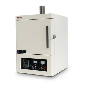
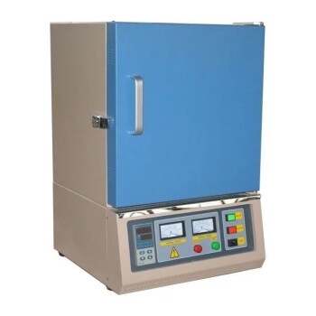
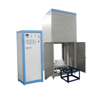
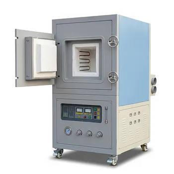
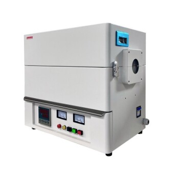
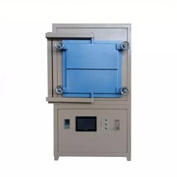
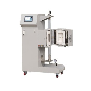
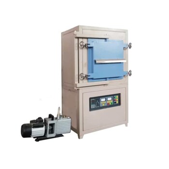
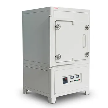
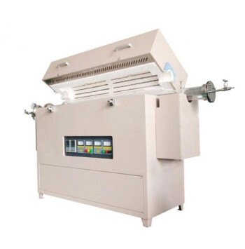
Take total control of your ceramic sintering kinetics with industry-leading heating technology from KINTEK. As specialists in advanced laboratory equipment and consumables, KINTEK provides a comprehensive selection of high-temperature laboratory furnaces—including muffle, tube, rotary, vacuum, CVD, controlled atmosphere, dental, and induction melting furnaces—all fully customizable to support your specific dilatometry and research requirements.
Whether you need exceptional temperature uniformity, ultra-stable ramp rates, or strict atmosphere isolation to extract pure kinetic data, KINTEK delivers the reliability and performance your lab demands.
Ready to optimize your furnace heating profiles and elevate your research? Contact KINTEK today to discuss custom high-temperature furnace solutions tailored to your application!
Related Products
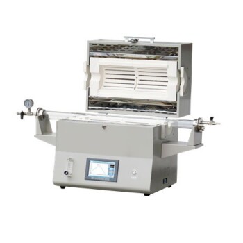
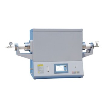
- 1400℃ High Temperature Laboratory Tube Furnace with Alumina Tube
- 1700℃ High Temperature Laboratory Tube Furnace with Alumina Tube
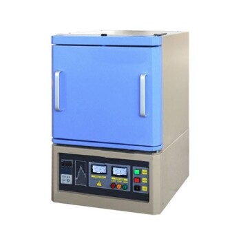
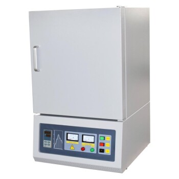
- 1800℃ High Temperature Muffle Oven Furnace for Laboratory
- 1700℃ High Temperature Muffle Oven Furnace for Laboratory
- 1200℃ Muffle Oven Furnace for Laboratory
People Also Ask
- How does zone-melting in tube furnaces synthesize bismuth micro-wires? Master Single-Crystal Thermoelectric Growth
- How do high-temperature laboratory tube furnaces ensure environmental stability? Precision Thermal Reduction Tips
- How are high-temp tube furnaces used to measure diffusion coefficients per Fick's law? Master Precision Annealing
- How are high-temperature laboratory tube furnaces applied in long-term vacuum homogenization heat treatments for intermetallic samples?
- How are high-temperature tube furnaces applied in testing ceramic-supported alloy membranes? Insights