Relative density is the master variable that dictates how a porous powder compact yields during pressure‑assisted sintering. At low density, the material behaves as a compressible body — its yield surface is an ellipse that depends heavily on hydrostatic pressure. As the compact densifies, this surface progressively expands and morphs into the classic von Mises cylinder, meaning that yielding eventually becomes insensitive to mean stress and is driven purely by shear. This evolution is why the load required to continue densification can rise dramatically, and why a lab furnace’s temperature‑pressure profile must be matched to the compact’s instantaneous relative density to reach full density without cracking.
The yield locus of a porous compact is not fixed; it is a moving target that shifts from an ellipse—where hydrostatic compression is essential to close pores—to a cylinder characteristic of incompressible dense metals. Programming an optimal hot‑press cycle in a high‑temperature furnace depends on understanding this density‑dependent transformation so that sufficient shear and reduced gas pressure are delivered at the right moments, preventing both under‑densification and fracture.
How Relative Density Re‑writes the Rules of Yielding
The Two‑Invariant Yield Condition for Porous Bodies
A loose powder compact is not a solid metal. Its yield behavior cannot be described by a single critical shear stress because the material can permanently change volume—pores collapse—under purely hydrostatic loading.
Consequently, the yield criterion must couple the first invariant of the stress tensor (hydrostatic pressure, (I_1)) with the second invariant of the stress deviator (shear stress, (I'_2)).
This coupling produces a closed yield surface in stress space, classically an ellipse, inside which the compact behaves elastically. Once the stress state touches that ellipse, plastic flow begins with a volumetric component that reduces porosity.
The Transition from an Ellipse to a Cylinder
As sintering proceeds and relative density ((\rho)) climbs toward 1.0, the yield locus does not simply expand—it changes shape.
At intermediate densities (roughly 0.7–0.95), the ellipse is still present, but its size grows and its eccentricity shifts. The material can still yield under hydrostatic tension or compression, but the magnitude of pressure required increases.
When full density is approached, pore‑free metal cannot yield under pure hydrostatic compression at practical pressures. The yield surface therefore degenerates into the familiar Huber‑Mises cylinder, open along the hydrostatic axis.
This means that in the final stage, any further plastic deformation—and any final elimination of isolated porosity—must be driven by deviatoric (shear) stress, not by mean stress alone.
Why This Matters for Pressure Application
Because the yield surface grows and morphs, the effective flow stress of the compact rises with density, often by an order of magnitude.
A low‑density green compact may yield at a few tens of MPa under a moderate uniaxial load, while a near‑fully‑dense compact requires hundreds of MPa to flow.
Moreover, the type of stress that causes yielding changes: early on, a hydrostatic component is highly effective at collapsing interconnected pores; near the end, only the shear component of a uniaxial or isostatic press can trigger the matrix plasticity needed to remove the last isolated voids.
A laboratory hot press that maintains a constant load throughout the cycle will therefore see an initially rapid densification followed by a stall—unless the load is deliberately increased as the density‑dependent yield surface expands.
Practical Furnace‑Cycle Design Informed by Yield Evolution
Programming Heating and Load Curves
Researchers using high‑temperature atmosphere or vacuum furnaces can exploit the density‑yield relationship to achieve maximum final density without defects.
During the early stage, when relative density is low, moderate pressure suffices to collapse interconnected pores; the furnace can be ramped while holding a relatively low load to allow gas to escape.
As densification proceeds, the load must be increased in concert with the expanding yield surface, providing the additional shear that the emerging von Mises behavior demands.
A common strategy is to hold the temperature at an intermediate level, apply a load that pushes the stress state just beyond the current yield ellipse, and then ramp the temperature further only after the density has increased enough to prevent swelling.
Avoiding Swelling and Gas Entrapment
A subtle danger arises when the yield surface shifts prematurely. If external pressure closes surface‑connected pores before volatile species have escaped, entrapped gases can build up internal pressure that later opposes densification.
When the compact is heated further, the yield surface might still be low enough that the internal gas pressure plus thermal stress can push the material back into the plastic regime, causing anomalous swelling—even a net loss of density.
Using a high‑temperature laboratory furnace with precise vacuum degassing cycles or a reducing gas flow (such as hydrogen) ensures that volatile species are removed while the yield surface is still “open” enough to allow gas migration. Only after degassing should the load be increased to drive the density into the range where the elliptical yield surface finally closes.
Understanding the Trade‑offs and Hidden Pitfalls
The Swelling Risk vs. Early Densification Pressure
Applying a high compaction pressure at room temperature can create a high green density and a promisingly small pore volume. However, if this sealing pressure traps gas‑forming impurities inside closed pores, the compact may later swell at 500–800 °C, undoing the initial gain.
The yield surface’s evolution then works against you: as the density temporarily drops during swelling, the yield ellipse shrinks, making it easier for further internal pressure to drive additional expansion.
Counteracting this requires a furnace cycle that pairs a slow heating rate with a low initial mechanical load, allowing gases to exit through still‑open channels before the pores pinch off.
Particle Size and Microstructural Heterogeneity
Fine powders (∼1 µm) generate a much larger intrinsic sintering stress—the capillary‑driving force from pore curvature—which accelerates early densification and shifts the yield ellipse upward more rapidly.
If the green body is packed heterogeneously, some regions will densify faster, creating local density gradients. The yield surface then varies spatially; parts that reach full density early behave as incompressible solids, while neighboring porous zones still require hydrostatic‑assisted flow.
These mismatches can concentrate stress, leading to shear localization or micro‑cracks. In a lab furnace, this risk is managed by using well‑dispersed powders and applying isostatic or near‑isostatic pressure early on to smooth out density gradients before the yield surface becomes too non‑uniform.
Making the Right Choice for Your Sintering Goal
Whether you are aiming for full density, tight dimensional control, or minimal grain growth, your hot‑press cycle must respect the moving yield surface.
- If your primary focus is reaching near‑theoretical density: Ramp the applied load in step with the density increase. Start with moderate pressure for degassing, then systematically increase the load to overcome the growing yield ellipse and finally supply enough shear to close the last pores.
- If your primary focus is preventing swelling in reactive powder systems: Use a vacuum hold or a hydrogen flow below the pore‑closure temperature to remove volatile species while the interconnected porosity is still open. Delay the high‑pressure phase until after degassing is complete.
- If your primary focus is minimizing grain growth while densifying fine powders: Exploit the high sintering stress of fine particles by applying only light external pressure early on, allowing capillary forces to drive densification. Increase the external load only when the density reaches the range where the yield surface demands it, thereby keeping temperatures as low as possible.
- If your primary focus is avoiding cracking in complex‑shaped parts: Pre‑sinter at a low load to homogenize density before the yield surface becomes highly density‑sensitive. Then apply the final pressure under conditions where the compact is already sufficiently uniform to deform as a continuum without localized failure.
The yield surface of a porous compact is not a static material property—it is a dynamic map of how close you are to full density. Treat it as such, and your laboratory furnace becomes a precision tool for delivering fully dense, defect‑free components with exactly the pressure and heat profile the material needs at every instant.
Summary Table:
| Densification Stage | Relative Density (ρ) | Yield Surface Shape | Primary Stress Driver | Furnace Cycle Strategy |
|---|---|---|---|---|
| Early Stage | Low (< 0.70) | Closed Ellipse (Compressible) | Hydrostatic Pressure | Low load, hold for degassing/vacuum to prevent gas entrapment |
| Intermediate Stage | Medium (0.70 – 0.95) | Expanding Ellipse | Combined Hydrostatic + Shear | Ramp load in step with density to match rising flow stress |
| Final Stage | Near Full (> 0.95) | Huber-Mises Cylinder | Shear (Deviatoric Stress) | Apply maximum shear/load to collapse final isolated voids |
Ready to achieve defect-free, fully dense components in your pressure-assisted sintering research? At KINTEK, we specialize in high-performance laboratory equipment and consumables. Our comprehensive range of customizable high-temperature furnaces—including vacuum, atmosphere, tube, muffle, CVD, and hot-press systems—delivers the precise thermal and mechanical control required to master complex, density-dependent yield behavior. Contact us today to discover how KINTEK can tailor the ultimate high-temperature furnace solution for your laboratory!
Related Products
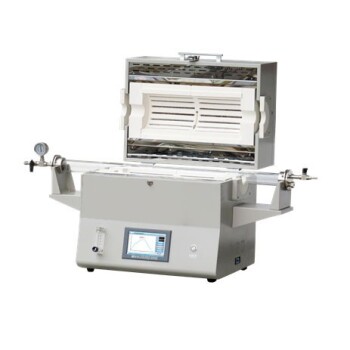
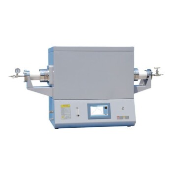
- 1400℃ High Temperature Laboratory Tube Furnace with Alumina Tube
- 1700℃ High Temperature Laboratory Tube Furnace with Alumina Tube
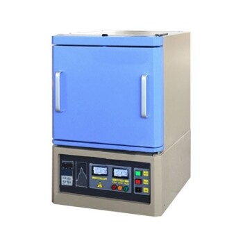
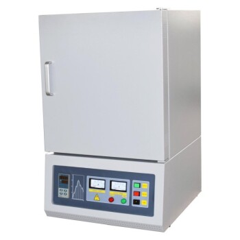
- 1800℃ High Temperature Muffle Oven Furnace for Laboratory
- 1700℃ High Temperature Muffle Oven Furnace for Laboratory
- 1200℃ Muffle Oven Furnace for Laboratory
People Also Ask
- How does zone-melting in tube furnaces synthesize bismuth micro-wires? Master Single-Crystal Thermoelectric Growth
- How do high-temperature laboratory tube furnaces ensure environmental stability? Precision Thermal Reduction Tips
- How are high-temperature laboratory tube furnaces applied in long-term vacuum homogenization heat treatments for intermetallic samples?
- How are high-temp tube furnaces used to measure diffusion coefficients per Fick's law? Master Precision Annealing
- How are high-temperature tube furnaces applied in testing ceramic-supported alloy membranes? Insights