The dihedral angle is the master switch for liquid-phase distribution. During liquid-phase sintering, the angle (\phi) formed at solid–liquid–solid junctions—governed by the ratio of grain-boundary energy to solid–liquid interfacial energy—dictates whether the second phase remains trapped in isolated corners or spreads into a continuous three‑dimensional network. When (\phi > 60^\circ), the liquid retracts into discrete pockets; as (\phi) drops to (60^\circ) and below, it penetrates along grain edges, and at (\phi = 0^\circ), it wets every boundary, completely separating the grains.
The dihedral angle translates interfacial energy balance into a predictable microstructure. Mastering the (\phi = 60^\circ) threshold and the full spectrum from (0^\circ) to (120^\circ) allows researchers to engineer densification, grain growth, and even shape retention in high‑temperature laboratory furnaces.
The Physics Behind the Dihedral Angle
A Balance of Interfacial Energies
The dihedral angle emerges from a thermodynamic tug‑of‑war. At every grain junction, the solid–solid grain‑boundary energy ((\gamma_{SS})) pulls grains together, while the solid–liquid interfacial energy ((\gamma_{SL})) resists penetration. The angle adjusts until these forces reach local equilibrium.
The Critical Angle Equation
The relationship is captured by the Young‑Dupré‑type balance:
[ \gamma_{SS} = 2 \gamma_{SL} \cos(\phi/2) ]
When the ratio (\gamma_{SS}/\gamma_{SL}) is large, (\phi) is small—indicating that the liquid wets the solid well. As the ratio decreases, (\phi) increases and the liquid phase recedes. This single equation is the key to predicting the second‑phase morphology long before a furnace cycle begins.
Morphology Map: How (\phi) Governs Second-Phase Distribution
Complete Grain‑Boundary Wetting ((\phi = 0^\circ))
At (\phi = 0^\circ) ((\gamma_{SS}/\gamma_{SL} \ge 2)), the liquid phase completely replaces solid–solid grain boundaries. A continuous film coats every grain, eliminating direct solid‑solid contact. The compact loses all structural rigidity and can slump under its own weight if not supported.
The Continuous Network Regime ((0^\circ < \phi \le 60^\circ))
When the dihedral angle is between (0^\circ) and (60^\circ) ((\gamma_{SS}/\gamma_{SL}) between 1.73 and 2), the liquid penetrates along three‑grain edges, forming an interpenetrating skeleton. The second phase remains continuous but no longer blankets every boundary—some solid‑solid contacts persist, restoring partial rigidity while still enabling capillary‑driven rearrangement.
Isolated Pockets ((\phi > 60^\circ))
Above (60^\circ) ((\gamma_{SS}/\gamma_{SL} < 1.73)), the liquid retracts to isolated pockets at grain corners and triple junctions. The solid‑solid grain‑boundary area increases dramatically. Because the liquid no longer forms a connected network, capillary forces are weaker, and densification slows. The second phase becomes entrained as discrete, lenticular pores or droplets.
The Special Case of (\phi \ge 120^\circ)
At very high angles ((\phi \ge 120^\circ), (\gamma_{SS}/\gamma_{SL} \le 1)), the liquid is confined even more tightly—to four‑grain junctions only—with minimal penetration. This often leads to poor densification and trapped porosity, as the liquid phase cannot efficiently redistribute material.
The Dynamic Evolution of Sintering Microstructures
Densification and Capillary Forces
The dihedral angle determines not only the final distribution but also the very mechanism of densification. At low (\phi) (e.g., ~10°), strong compressive capillary forces pull particles together, enabling rapid particle rearrangement and viscous flow. When (\phi) exceeds about (60^\circ), those forces become repulsive, causing swelling rather than shrinkage.
Kinetic Film Formation During Extended Holds
Microstructure continues to evolve even after the furnace reaches peak temperature. During long soaks in high‑purity atmospheres, impurity segregation can reduce the solid‑liquid interfacial energy locally, causing liquid films to nucleate and thicken at originally dry grain boundaries. A furnace capable of holding a stable (1350^\circ\text{C}) for 50 hours can thus drive a system from an apparently high‑angle morphology to one with nanometer‑thick intergranular films.
Practical Implications for High‑Temperature Laboratory Furnaces
Temperature, Atmosphere, and Interfacial Control
Every variable a furnace operator commands—peak temperature, dwell time, heating rate, and gas atmosphere—directly tunes (\gamma_{SS}/\gamma_{SL}). Even a shift of a few degrees can alter the dihedral angle enough to switch from a continuous network to isolated pockets. High‑performance atmosphere or vacuum furnaces allow the precise, stable thermal profiles needed to lock in the desired interfacial energy ratio.
Balancing Densification Against Shape Distortion
The pursuit of low dihedral angles for rapid densification must be tempered by the risk of slumping. At (\phi = 0^\circ), complete wetting eliminates all solid‑solid bonding, causing the component to lose its shape. For many ceramic and metal systems, the ideal process window lies in the (0^\circ < \phi \le 60^\circ) range, where capillary forces drive shrinkage while a solid skeleton maintains dimensional accuracy.
Understanding the Trade‑offs
Slumping at Low Angles
The drive toward zero‑angle wetting can be a double‑edged sword. While a thin continuous film accelerates mass transport, it also removes the structural backbone of the compact. Components can sag, warp, or even melt into the setter unless the temperature profile and support system are designed to prevent collapse.
Swelling and Incomplete Densification at High Angles
At the other extreme, high dihedral angles ((>90^\circ)) create repulsive capillary pressures that push particles apart. Instead of shrinking, the compact blows up with large, stable pores. Achieving high density in such systems requires long hold times, external pressure (sinter‑forging), or compositional modifications to reduce (\gamma_{SS}/\gamma_{SL}).
Making the Right Choice for Your Sintering Goal
Leverage the dihedral angle by matching your furnace cycle to your desired microstructure:
- If your primary focus is maximum densification and uniformity: Target a dihedral angle in the low (0^\circ<\phi\le 30^\circ) range by introducing wetting additives and using a slow, controlled ramp to peak temperature.
- If your primary focus is retaining precise component shape: Keep (\phi) safely above (0^\circ) (typically (10^\circ)–(30^\circ)) to maintain a rigid solid skeleton while still benefiting from capillary‑driven rearrangement.
- If your primary focus is grain‑boundary engineering for functional properties: Operate in the (30^\circ)–(60^\circ) window, where a continuous but not fully wetting liquid network can tailor grain growth and boundary chemistry.
- If your primary focus is studying kinetic thin‑film evolution: Use a furnace with excellent long‑term stability to apply extended dwell times, allowing impurity segregation to drive (\phi) toward lower local values and generate nanoscale intergranular films.
Master the dihedral angle, and you master the roadmap from powder to performance in any high‑temperature liquid‑phase sintering process.
Summary Table:
| Dihedral Angle (ϕ) | Energy Ratio (γ_SS / γ_SL) | Second-Phase Morphology | Sintering & Structural Impact |
|---|---|---|---|
| ϕ = 0° | ≥ 2.0 | Complete boundary film | Maximum wetting; fast densification but high risk of slumping |
| 0° < ϕ ≤ 60° | 1.73 – 2.0 | Continuous 3D edge network | Capillary-driven shrinkage with solid skeleton shape retention |
| 60° < ϕ < 120° | < 1.73 | Isolated pockets at junctions | Reduced capillary force; slower densification and larger grain contact |
| ϕ ≥ 120° | ≤ 1.0 | Confined to 4-grain junctions | Poor liquid transport; leads to trapped porosity or swelling |
Unlock Precise Microstructural Engineering with KINTEK Furnaces
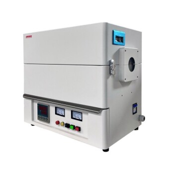
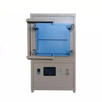
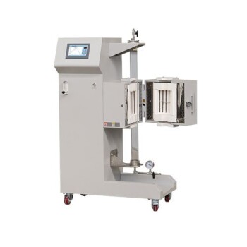
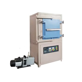
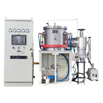
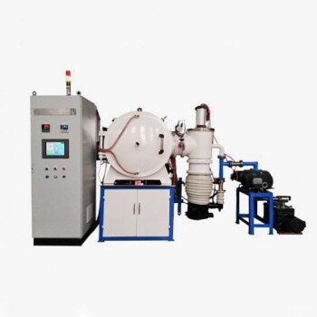
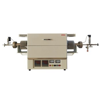
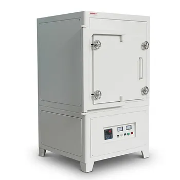
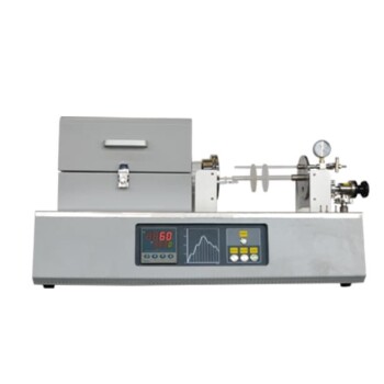
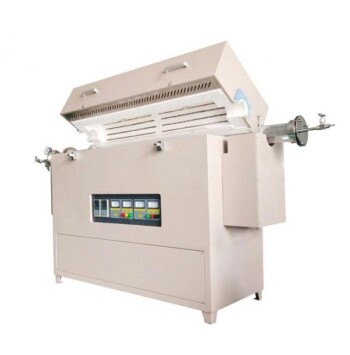
Achieving the exact dihedral angle required for optimal liquid-phase sintering demands unyielding temperature stability and precise atmosphere control. KINTEK offers a comprehensive range of advanced high-temperature laboratory furnaces—including vacuum, atmosphere, muffle, tube, CVD, and custom-designed furnaces—tailored to support complex material synthesis and high-temperature research.
Whether you are refining ceramic densification, preventing shape slumping, or studying intergranular film kinetics, our expert team is here to support your laboratory's unique requirements.
Contact KINTEK Sintering Experts Today
Related Products
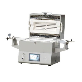
- 1400℃ High Temperature Laboratory Tube Furnace with Alumina Tube
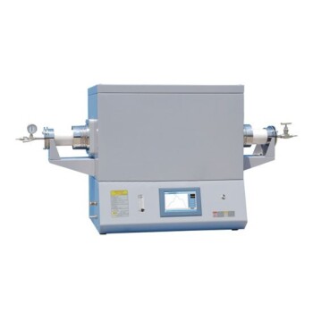
- 1700℃ High Temperature Laboratory Tube Furnace with Alumina Tube
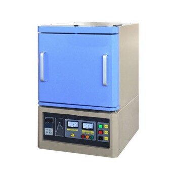
- 1800℃ High Temperature Muffle Oven Furnace for Laboratory
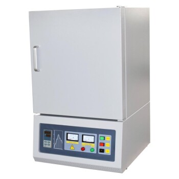
- 1700℃ High Temperature Muffle Oven Furnace for Laboratory
- 1200℃ Muffle Oven Furnace for Laboratory
People Also Ask
- How does zone-melting in tube furnaces synthesize bismuth micro-wires? Master Single-Crystal Thermoelectric Growth
- How are high-temp tube furnaces used to measure diffusion coefficients per Fick's law? Master Precision Annealing
- How are high-temperature laboratory tube furnaces applied in long-term vacuum homogenization heat treatments for intermetallic samples?
- How do high-temperature laboratory tube furnaces ensure environmental stability? Precision Thermal Reduction Tips
- How are high-temperature tube furnaces applied in testing ceramic-supported alloy membranes? Insights