The evolution of electrical resistance and heat generation during high-temperature resistance sintering is a story of collapsing contact barriers, shifting energy landscapes, and a relentless drive toward uniformity. It begins with a microsecond-scale dielectric breakdown that sends resistance plummeting, transitions through a stage where heat spreads from inter-particle bridges into the bulk particles, and finally settles into a regime where the densified compact’s own resistivity—and often overlooked machine interfaces—governs the entire thermal profile. Understanding this progression lets you time pressure, tune electrical pulses, and avoid the hidden temperature errors that quietly ruin compact quality.
The resistance of the powder compact does not fall smoothly; it crashes, stabilizes, and then rises slightly as temperature takes over. At the same time, heat generation moves from intense, localized sparks at particle contacts to a distributed, bulk-heating mode. Failing to account for the stage-dependent resistance and the critical role of punch–compact contact resistances can leave your simulated temperatures 150 °C colder than reality, leading to under-sintering, structural defects, or outright material failure.
Deconstructing the Resistance and Heat Evolution Across the Sintering Cycle
The electrical and thermal behavior of a powder compact under high-temperature sintering is not a single event—it is a three-act play. Each stage is defined by a distinct physical process that controls where and how heat is generated.
Stage 1: The Initial Breakdown — Microseconds of Collapsing Resistance
Everything starts with the insulating oxide films that naturally coat every particle surface. Before current flows, the compact’s total resistance is dominated by these high-resistance barriers at the inter-particle contact points.
Within the first 10–20 microseconds of applying an electric field, a dielectric breakdown occurs. The oxide layers are pierced by a sudden discharge, instantly transforming near-infinite contact resistance into a conductive pathway.
This breakdown triggers a sharp, near-vertical drop in overall compact resistance. Heat generation during this instant is intensely localized at the newly formed contact points—think of it as microscopic lightning bolts fusing particles together.
As the microseconds roll on (typically 100–200 µs into the pulse), the resistance decrease slows. It may even start to rise slightly because the Joule heating at the contacts now increases the local temperature, which for most materials slightly elevates resistivity. This subtle upturn is a direct signal that the heating front is beginning to spread.
Stage 2: The Intermediate Transition — Heat Begins to Share the Load
Once the oxide films are broken and contact zones have started to grow, the situation changes fundamentally. The contact resistance is no longer the sole villain; it is now a partner with the bulk resistance of the particles themselves.
During this stage, particle softening and the expansion of the inter-particle necks mean that current can flow through larger, lower-resistance bridges. Heat generation becomes distributed across both the inter-particle contacts and the body of the powder particles.
The visual picture: instead of isolated hotspots, you get a glowing network of particle boundaries with the particle cores beginning to heat up. The compact resistance continues to fall, but now the rate of decrease is more gradual, reflecting the growing metallic cross-section.
This is the stage where uniform densification truly begins. If energy input is too aggressive here, local melting can occur before the bulk has a chance to soften, locking in defects. If it’s too timid, the compact never reaches the plastic state needed for collapse.
Stage 3: The Later Regime — When Bulk and Interfaces Take Over
As densification proceeds, the initial inter-particle contact resistance becomes negligible. The sintered body now behaves increasingly like a monolithic solid.
In this final stage, heat generation is no longer controlled by the powder’s internal contact points. Instead, three other resistances become dominant:
- The inherent resistivity of the densified compact itself, now approaching its theoretical bulk value.
- The punch-to-compact electrical contact resistance, where the copper punches meet the sample surface.
- The internal machine resistance, including cables, electrodes, and joints.
These often-overlooked vertical contact resistances at the punch–die–sample interfaces create additional heat dissipation pathways and significantly alter the current distribution. Experiments show that ignoring these contacts in thermal models causes a staggering 138 °C to 172 °C underestimation of the actual sample and die temperatures.
Operationally, this means that even when the powder is fully densified, your temperature control error can balloon if you haven’t calibrated for contact resistances. The machine effectively inserts hidden heaters at every mechanical interface.
The Hidden Dance: Contact Resistances and Circuit Tuning
The internal resistance evolution is not an isolated story—it interacts directly with the sintering machine’s electronic character.
Why the Rapid Resistance Change Can Destroy Your Sample
During the initial discharge, the moving resistance value determines the circuit behavior. The relationship between the instantaneous resistance (R(\tau)), the circuit inductance (L), and the capacitance (C) dictates whether the electrical pulse is aperiodic (a single, controlled surge) or a damped sinusoid (an oscillating, ringing waveform).
If (R^2(\tau) > 4L/C), the discharge is aperiodic—energy is delivered in one smooth pulse, ideal for controlled heating. If (R^2(\tau) < 4L/C), the current oscillates, bouncing energy back and forth multiple times. This repetitive heating can cause excessive energy dissipation, localized melting, and structural defects, especially if the compact resistance hasn’t bottomed out yet.
Therefore, the early-stage resistance drop is not just a physical curiosity; it’s a circuit-tuning parameter. Operators must ensure that the machine’s LC components are matched to the powder’s expected resistance profile to avoid destructive ringing.
Why Your Model Is Almost Certainly Wrong Without Contact Resistances
The punch–compact and punch–die interfaces are not perfect conductive contacts. They introduce significant electrical and thermal resistance, especially at the high pressures and temperatures of sintering.
Neglecting these contacts in simulation means you miss entire heating zones. Current does not flow uniformly; it crowds through the lowest-resistance paths, creating hot zones near the punches that the model ignores. The result is a modeled temperature that can be over 150 °C too low, leading to under-sintered cores or thermal runaway at the edges.
Correctly accounting for contact resistances is not optional—it is the difference between a predictable process and a guessing game.
Common Pitfalls and Trade-offs to Avoid
Knowing the evolution is one thing; navigating the process without making critical mistakes is another.
Pitfall 1: Treating the Initial Resistance Drop as a Simple On/Off Event
A common mistake is to assume the oxide breakdown is complete after the first few microseconds. In reality, the resistance continues to evolve gradually, and any secondary dielectric barriers may break down later under higher fields. Applying full pressure before the resistance stabilizes can create uneven load transfer and shear defects.
Takeaway: Match the pressure ramp to the resistance plateau, not the initial breakdown spike.
Pitfall 2: Designing the Energy Cycle Without Considering Circuit Damping
If your discharge circuit is not designed to remain in the aperiodic regime throughout the resistance drop, you risk oscillatory heating. The trade-off: a circuit overdamped for the initial low resistance might under-deliver energy later, while one optimized for the later stage may ring violently at the start.
Solution: Use a pulse-shaping strategy that dynamically adjusts pulse energy or bank configuration as the resistance changes. This often means segmenting the sintering cycle into pre-heat, breakdown, and bulk-heating pulses.
Pitfall 3: Ignoring the Temperature Feedback on Resistance
As the compact heats, its resistivity generally increases (for metals). This positive feedback can cause a runaway in the later stages if the machine is in constant-current mode, as a rising resistance with fixed current produces more heat. Conversely, in constant-voltage mode, the current may drop, slowing densification.
Trade-off awareness: Choose your power-control mode based on the expected resistance trajectory in the later stage. Constant power control often offers the most stable thermal profile.
Pitfall 4: Forgetting That the Machine Itself Is a Heater
Internal machine resistance is not a constant—it can change as cables and joints heat up. This causes a slow drift in the total circuit resistance, shifting the energy delivery months or years after calibration. Regular cold-resistance checks and using four-wire (Kelvin) monitoring directly at the punches can mitigate this.
Making the Right Choice for Your Process Goal
The evolution of resistance and heat generation is not just a lesson in physics; it is your primary control map for achieving target density, microstructure, and cycle time. Your operational decisions must align with the stage you’re in.
- If your primary focus is uniform densification without hot cracking: Delay the application of full force until the intermediate stage when heat generation is distributed across the particles. This prevents cold welding at isolated contacts and allows the bulk to soften before compaction.
- If your primary focus is minimizing cycle time: Use a high-energy initial pulse to rapidly break down oxides and kick-start contact growth, but immediately transition to a lower, controlled power level to avoid ringing and overheating. Monitor the circuit’s damping factor in real time.
- If your primary focus is experimental reproducibility and accurate process modeling: Calibrate your machine’s contact resistances at the punch–sample–die interfaces using a reference compact with known bulk resistivity. Feed these values into your thermal model—your simulated temperatures will gain over 100 °C of accuracy instantly.
- If your primary focus is processing poorly conductive or oxide-heavy powders: Pre-condition the powder with a low-energy, high-frequency pre-pulse sequence to gradually dissolve surface contaminants. This stretches the initial breakdown stage but prevents catastrophic localized arcing.
Master the resistance arc, and you master the heat. The moment you treat the compact’s electrical evolution not as a nuisance but as a real-time process signature, your control over high-temperature sintering becomes absolute.
Summary Table:
| Stage | Key Mechanism | Resistance Behavior | Heat Generation Zone | Primary Operational Focus |
|---|---|---|---|---|
| 1. Initial Breakdown | Oxide layer dielectric breakdown (10–200 µs) | Rapid vertical drop, followed by a slight thermal upturn | Microscopic sparks at particle contact points | Avoid oscillatory ringing; match pressure to resistance plateau |
| 2. Intermediate Transition | Inter-particle neck growth & bulk softening | Gradual decrease along expanding metallic paths | Distributed across particle contacts and cores | Balance energy input to ensure uniform bulk softening without local melting |
| 3. Later Regime | Full densification approaching monolithic solid | Governed by bulk material & machine interface resistivity | Bulk compact + punch-compact contact interfaces | Calibrate interface contact resistance to eliminate severe thermal errors |
Mastering precise thermal profiles and heat control is essential for faultless material densification. At KINTEK, we specialize in advanced laboratory equipment and high-temperature solutions engineered for ultimate process control. Whether you require customizable muffle, tube, rotary, vacuum, CVD, atmosphere, dental, or induction melting furnaces, our equipment helps you eliminate thermal errors and achieve superior microstructures.
Ready to optimize your high-temperature processing? Contact KINTEK today to consult with our high-temp furnace experts!
Related Products
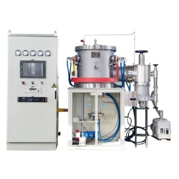
- 2200 ℃ Tungsten Vacuum Heat Treat and Sintering Furnace
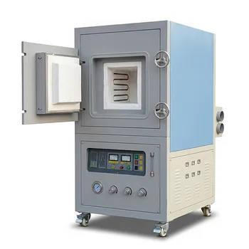
- High Temperature Muffle Oven Furnace for Laboratory Debinding and Pre Sintering
- 2200 ℃ Graphite Vacuum Heat Treat Furnace
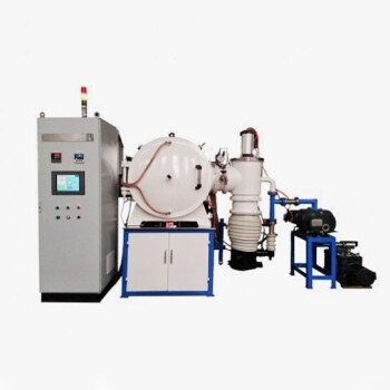
- Vacuum Heat Treat Sintering Furnace Molybdenum Wire Vacuum Sintering Furnace
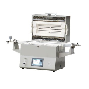
- 1400℃ High Temperature Laboratory Tube Furnace with Alumina Tube
People Also Ask
- How does a tungsten-heated vacuum sintering furnace prepare (TbxY1-x)2O3 ceramics? Achieve 99%+ Density & Purity
- What wear-resistance enhancements are achieved by powder coating? The Role of Vacuum Sintering Furnaces
- How do compaction pressure and vacuum sintering optimize porous ceramics? Maximize Density & Toughness
- What role does a high-temperature vacuum sintering furnace play in the densification of WC-10(Ni, Ni/Co) alloys?
- How does high-temp vacuum sintering influence Y-TZP mechanical properties? Achieve Max Toughness