Gel thickness, permeability, and liquid viscosity don’t just passively influence drying—they are the three physical levers that directly set the internal tensile stress responsible for cracking. A thicker gel film or body, a higher-viscosity pore liquid, or a lower matrix permeability all amplify the microscopic pressure gradients that tear the fragile gel network apart. In a flat plate dried from both faces, the macroscopic tensile stress at the surface scales as (\sigma_x \approx \frac{L \eta_L \dot{V}_E}{3K}): it rises linearly with half‑thickness (L) and liquid viscosity (\eta_L), and falls inversely with permeability (K).
Cracking in sol‑gel ceramics is a race between the tensile stress generated by evaporation‑driven pressure gradients and the gel’s fracture toughness. Because the stress equation puts thickness and viscosity in the numerator and permeability in the denominator, every practical strategy to avoid drying fractures boils down to reducing (L) or (\eta_L), increasing (K), or aggressively limiting the evaporation rate (\dot{V}_E).
The Physics of Drying Stress in Sol‑Gels
The Critical Point: Transition from Constant to Falling Rate
Drying begins with liquid menisci flush with the external surface—the Constant Rate Period (CRP).
As liquid evaporates, the menisci retreat into the pore channels, creating a concave liquid‑vapor interface.
Capillary forces generate negative pressure in the pore liquid, pulling the solid network inward and imposing massive tensile stress—often 4 to 150 MPa.
The highest risk of fracture arrives at the critical point when the liquid front becomes pinned and the CRP gives way to the Falling Rate Period.
At that moment, a steep spatial pressure gradient ((\nabla p)) builds through the thickness, driving differential strain that cracks the body if the stress exceeds the network’s tolerance.
Deriving the Stress Equation
For a flat gel of thickness (2L) drying symmetrically from both faces, the macroscopic in‑plane tensile stress at the drying surface is:
[ \sigma_x \approx \frac{L \eta_L \dot{V}_E}{3K} ]
Here, (L) is the half‑thickness, (\eta_L) the dynamic viscosity of the pore liquid, (\dot{V}_E) the volumetric evaporation rate per unit area, and (K) the permeability of the gel matrix (m²).
The equation captures the balance between the viscous drag that resists fluid flow through the pores and the capillary suction that drives it.
How Thickness Multiplies Stress
Thickness appears linearly in the numerator: doubling the gel half‑thickness doubles the nominal stress.
A thicker body forces the liquid to travel a longer path to reach the surface, creating larger pressure differentials and steeper gradients.
Bulk monoliths, therefore, are far more cracking‑prone than thin films under identical evaporation conditions, explaining why sol‑gel monoliths are notoriously difficult to dry without special measures.
The Role of Liquid Viscosity
Higher (\eta_L) also increases (\sigma_x) proportionally because it intensifies the viscous pressure drop as liquid flows through the nanoscale channels.
Typical sol‑gel precursors contain water or alcohol; replacing them with a lower‑viscosity solvent (e.g., acetone) directly reduces the driving stress.
However, the choice of solvent must not weaken the gel network or alter the chemistry unfavorably—a classic trade‑off.
Permeability as the Pressure‑Relief Valve
Permeability (K) sits in the denominator: raising it lowers the stress.
Permeability reflects how easily liquid can flow through the interconnected pore network; wider, more connected pores offer less resistance.
Introducing colloidal silica particles into a precursor solution or using drying control chemical additives (DCCAs) to coarsen the pore structure can raise (K) ten‑fold, drastically reducing cracking tendency—even if the accompanying larger pores may slightly weaken the dry skeleton.
From Stress to Cracks: The Flaw Sensitivity
Stress Concentration at Pore Flaws
The macroscopic stress (\sigma_x) alone does not cause fracture; it is the local stress at a flaw tip that matters.
Pores, surface scratches, and internal heterogeneities act as stress‑concentrators, amplifying the macroscopic stress according to (\sigma_c = \sigma_x \sqrt{\pi c}), where (c) is the effective flaw length.
When Local Stress Exceeds Fracture Toughness
Crack propagation initiates when the stress intensity at the flaw tip exceeds the gel’s fracture toughness (K_{IC}).
Thus, a gel with low permeability, high liquid viscosity, or large thickness not only generates a high macroscopic stress but also provides the driving force for even relatively small flaws to become unstable.
The practical outcome: the same gel composition that works perfectly as a 1‑µm film may shatter as a 5‑mm monolith.
Thermal Processing Beyond Drying: New Stress Landscapes
Sintering Shrinkage and Constrained Film Stresses
Drying is only the first thermal hurdle. During subsequent high‑temperature sintering, the dried gel densifies.
Thin films deposited on a rigid substrate are constrained from shrinking in‑plane, so all densification strain must come from the thickness direction. This 1D constraint generates high tensile stress that can cause cracking or delamination if the film exceeds a critical thickness—typically around 1 µm for sol‑gel films.
How Drying‑Induced Flaws Persist into Firing
Cracks that form during drying do not heal; they become pre‑existing flaws for the sintering stage.
Even if the drying protocol barely avoids fracture, the stress concentrations around near‑surface pores are carried into the furnace, where constrained shrinkage pushes them over the edge. Therefore, the drying step’s parameters ((L, \eta_L, K)) indirectly set the baseline defect population that determines ultimate sintering success.
Understanding the Trade‑offs
Manipulating thickness, permeability, and viscosity always involves compromises:
- Increasing permeability by enlarging pores may reduce the green body’s mechanical strength and final density after sintering, making the part less robust in service.
- Lowering liquid viscosity through solvent exchange can accelerate drying, but the new solvent might dissolve precursor oligomers or interfere with network condensation, weakening the gel.
- Reducing thickness is often limited by the final part geometry—monolithic lenses or bulk catalyst supports cannot simply become films.
- Suppressing the evaporation rate (\dot{V}_E) with slow, controlled heating mitigates stress but drastically extends processing time and can introduce gradient aging effects that alter the gel structure.
The art of sol‑gel processing is to balance these levers so that the peak stress stays safely below the gel’s flaw‑dependent fracture strength, without sacrificing the final material’s performance.
Making the Right Choice for Your Goal
Use the following decision guide to align your processing parameters with your primary objective:
- If your primary focus is producing an un‑cracked monolith: Maximize permeability by incorporating pore‑forming additives or colloidal silica, and employ the lowest‑viscosity solvent your chemistry allows, while drying at the slowest rate your timeline permits.
- If your primary focus is defect‑free thin films: Keep the film thickness well below the ~1 µm critical limit, ensure the substrate is perfectly clean for maximum adhesion, and ramp the furnace slowly through the initial low‑density stage to avoid pre‑sintering flaws.
- If your primary focus is rapid processing throughput: Choose a solvent system with both low viscosity and low surface tension, and design a heating profile that holds the evaporation rate constant at a value the gel can sustain—then use a high‑permeability pore structure to stay below the stress threshold.
- If your primary focus is maximizing final component strength: Accept the slower, low‑stress drying that preserves a fine‑pored, high‑green‑density network, and then sinter with minimal heating rates to prevent density‑gradient flaws from becoming critical.
With a clear understanding of how thickness, permeability, and viscosity drive the drying stress, you can deliberately engineer your sol‑gel process—rather than merely hoping the gel survives the oven.
Summary Table:
| Parameter | Physical Mechanism | Impact on Tensile Stress ($\sigma_x$) | Optimization Strategy |
|---|---|---|---|
| Gel Half-Thickness ($L$) | Extends liquid flow path; creates steeper internal pressure gradients. | Direct Linear Increase ($\sigma_x \propto L$) | Keep films $<1\ \mu\text{m}$ or slow drying for bulk monoliths. |
| Liquid Viscosity ($\eta_L$) | Increases viscous drag as pore fluid travels through nanoscale channels. | Direct Linear Increase ($\sigma_x \propto \eta_L$) | Perform solvent exchange to lower-viscosity fluids (e.g., acetone). |
| Matrix Permeability ($K$) | Defines ease of fluid flow; wider pores reduce hydraulic resistance. | Inverse Proportional ($\sigma_x \propto 1/K$) | Incorporate DCCAs or colloidal silica to coarsen pore structure. |
| Evaporation Rate ($\dot{V}_E$) | Drives capillary suction and fluid withdrawal velocity at surface menisci. | Direct Linear Increase ($\sigma_x \propto \dot{V}_E$) | Control humidity and ramp temperature gradually during CRP. |
Master Precision Thermal Processing with KINTEK
Prevent drying defects and achieve flawless ceramic densification with high-precision furnace technology. KINTEK specializes in premium laboratory equipment and consumables, offering a comprehensive range of high-temperature furnaces—including muffle, tube, vacuum, atmosphere, CVD, rotary, and induction melting furnaces—all fully customizable to meet your unique materials research requirements.
Whether you are processing delicate sub-micron sol-gel films or complex monolithic ceramics, our engineered thermal systems provide the exact temperature and atmospheric control needed to eliminate stress gradients.
Contact KINTEK Today to Optimize Your Ceramic Sintering Process
Related Products
- High Temperature Muffle Oven Furnace for Laboratory Debinding and Pre Sintering
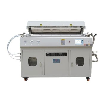
- High Pressure Laboratory Vacuum Tube Furnace
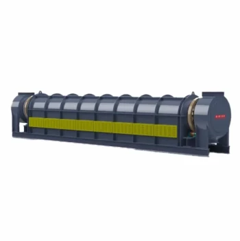
- Electric Rotary Kiln Pyrolysis Furnace Plant Machine Small Rotary Kiln Calciner
- Vacuum Heat Treat Sintering Furnace with Pressure for Vacuum Sintering
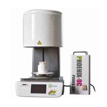
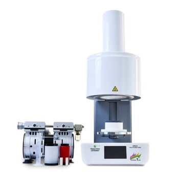
- Chairside Dental Porcelain Zirconia Sintering Furnace with Transformer for Ceramic Restorations
People Also Ask
- What thermal phenomena occur during polymer binder burnout in ceramic green bodies? Lab Furnace Guide
- Why is controlled heat treatment in a muffle furnace necessary for calcined clay? Achieve Optimal Pozzolanic Activity
- What role does a high-temperature muffle furnace play in STFO synthesis? Achieve Pure Perovskite Results
- How does a high-temperature muffle furnace facilitate the formation of LaNbxAl1−xO3+δ perovskite structures? Key Roles
- What role does a high-temperature muffle furnace play in the formation of biochar catalysts? Master Catalyst Synthesis