This is not just shrinkage measurement — it is mechanical spectroscopy.
By applying a precise, small uniaxial load to a ceramic powder compact inside a controlled-atmosphere high-temperature furnace and simultaneously tracking its axial and radial dimensions, you mathematically separate the volumetric densification rate from the creep strain rate. This decoupling directly exposes the intrinsic sintering stress — the thermodynamic driving force that pulls pores shut — and the material’s creep viscosity, giving you the data needed to predict and optimize densification without guesswork.
The central insight: a simple, carefully controlled mechanical load transforms a passive dilatometer into an active rheological probe. By measuring how a compact shrinks (densification) and flows (creep) under a known stress, you extract the material’s own sintering pressure and its resistance to deformation. Those numbers are the key to designing furnace cycles that maximize density while avoiding cracking or runaway grain growth.
The Core Principle: Decoupling Shrinkage from Deformation
How a Loading Dilatometer Works
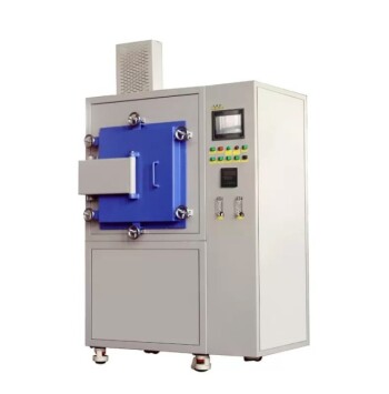
A cylindrical powder compact sits inside a high-temperature atmosphere furnace, subjected to a constant, small uniaxial load ($p_z$).
Throughout the heat treatment, a high-resolution dilatometry fixture continuously logs the specimen’s length ($L$) and radius ($R$). Because sintering involves large deformations, true strain rates are used:
$\dot{\varepsilon}_z = \frac{1}{L}\frac{dL}{dt}$ and $\dot{\varepsilon}_r = \frac{1}{R}\frac{dR}{dt}$.
These two measured rates contain all the mechanical information — they just need to be decoded.
Separating Densification from Creep
The total dimensional change mixes two distinct physical processes: pore removal (densification) and shear flow (creep).
A simple mathematical decomposition splits them apart:
-
Volumetric densification strain rate: $\dot{\varepsilon}_\rho = -\frac{1}{3}(\dot{\varepsilon}_z + 2\dot{\varepsilon}_r)$
This is the rate at which pore volume disappears, revealing how fast the compact is becoming fully dense. -
Creep strain rate: $\dot{\varepsilon}_c = \frac{2}{3}(\dot{\varepsilon}_z - \dot{\varepsilon}_r)$
This captures the shape‑change component — the viscous shear flow that can lead to distortion if not balanced.
With these two independent signals in hand, you can now interrogate the material’s intrinsic response to the applied load and to its own capillarity.
How the Measurement Quantifies Sintering Stress
The Constitutive Link Between Stress and Strain Rates
Sintering stress is not a direct measurement; it is extracted from the relationship between the applied load and the measured densification rate.
The constitutive law for densification under a hydrostatic stress $\sigma_m$ (where $\sigma_m = p_z/3$ for uniaxial loading) is:
$\dot{\varepsilon}\rho = \frac{\sigma_m - \Sigma}{\eta\rho}$
Here, $\Sigma$ is the sintering stress — the equivalent hydrostatic tension that pore surfaces exert as they try to shrink — and $\eta_\rho$ is the densification viscosity.
When the externally applied stress exactly balances the internal capillary stress, the densification rate goes to zero.
The Zero‑Densification‑Rate Method
In practice, you perform a series of loading dilatometry runs at different $p_z$ values, all at the same relative density.
Plot the measured $\dot{\varepsilon}\rho$ against $\sigma_m$, and **extrapolate the line to $\dot{\varepsilon}\rho = 0$**. The intercept on the stress axis is $\Sigma$.
The supplementary analysis of creep strain gives the creep viscosity $\eta_c$ via $\dot{\varepsilon}c = \sigma{eff}/\eta_c$, where the effective shear stress for this geometry equals $p_z$.
The ratio $\dot{\varepsilon}_\rho/\dot{\varepsilon}_c$ can also be used, in combination with multiple load points, to extract both $\Sigma$ and the stress intensification factor $\phi$ that couples shear to densification.
Seeing Microstructural Evolution in Real Time
As relative density climbs from, say, 0.70 to 0.95, the measured sintering stress often decreases — for example, dropping from 0.8 MPa to 0.4 MPa in alumina compacts.
This drop is not a loss of driving force; it is a sign of concurrent microstructural coarsening. When grain and pore sizes grow at high temperatures, the capillary pressure per unit area falls. Normalizing $\Sigma$ by grain size reveals that the intrinsic driving force actually increases with density, underlining why precise temperature control is essential to limit coarsening while maintaining densification.
The Critical Role of Atmosphere Control
Why the Furnace Atmosphere Is Not a Detail
The processing atmosphere inside a high-temperature furnace becomes a direct participant in the measurement when pores close off into isolated voids during final‑stage sintering.
If the furnace atmosphere contains a slow‑diffusing or inert gas, the trapped gas exerts an internal pressure ($P_i$) that opposes the capillary sintering stress. When $P_i$ equals $2\gamma_s/r_f$, densification halts — potentially corrupting your measured $\Sigma$.
Matching Atmosphere to Material
To obtain true material properties, the atmosphere must be chosen so that any entrapped gas can readily diffuse out through the lattice or grain boundaries.
For oxides, hydrogen or other fast‑diffusing gases prevent the build‑up of counter‑pressure, allowing the compact to approach theoretical density. Conversely, measurements in argon at 1 atm may still work for fine powders (pore radius below a few microns), but for larger pores or higher pressures, residual porosity becomes a measurement artifact. The high-temperature atmosphere furnace lets you switch between gases to isolate the intrinsic sintering stress from environmental effects.
Ensuring Accurate Data: The Importance of Temperature Uniformity
The Exponential Sensitivity of Diffusion
Solid‑state densification rates follow an Arrhenius temperature dependence: $\dot{\varepsilon}_\rho \propto D/T$, where $D$ is the diffusion coefficient.
A temperature fluctuation of only a few degrees can shift the atomic flux across particle necks by an order of magnitude, directly altering the measured strain rates. In a loading dilatometry experiment, this would masquerade as a change in sintering stress or viscosity.
Isothermal Precision as a Non‑Negotiable
The furnace must maintain strictly uniform temperature across the entire compact throughout the test. Any thermal gradients induce differential shrinkage and creep, mixing true material response with thermal‑expansion artifacts. Using slow, controlled heating ramps (e.g., 5 °C/min) and long holds ensures the strain‑rate signals you record are faithful to the sintering mechanisms, not to thermal transients.
Understanding the Trade‑offs
-
Inhomogeneous Deformation: Loading dilatometry assumes the compact densifies uniformly. In reality, friction between the pushrods and the specimen can create barrelling, biasing the radial strain measurement and distorting the extracted $\Sigma$.
-
Anisotropic Microstructure Development: The applied uniaxial load gives a slight preferential orientation to pore shrinkage. The extracted $\Sigma$ is an apparent sintering stress that depends on the load direction; using multiple stress states or keeping loads very low minimizes this effect.
-
Limited Load Range: The load must be small enough that creep does not dominate the signal, yet large enough to produce measurable differences in densification rate. This works best for fine‑grained ceramics where the capillary stress (typically 0.1–1 MPa) is comparable to the applied hydrostatic stress.
-
Atmosphere Cost: Switching between gases, maintaining ultra‑high purity, or using hydrogen requires additional safety infrastructure. For oxide ceramics, an inert‑gas pre‑purge followed by a reducing atmosphere is often the practical compromise.
Making the Right Choice for Your Goal
The loading dilatometry experiment you design should match your specific needs. Use these guidelines:
-
If your primary focus is optimizing a hot‑pressing or pressure‑assisted sintering cycle: Extract both $\Sigma$ and $\eta_c$ across the full density range. Use the densification‑viscosity curve to set pressure profiles that stay just above the sintering stress, minimizing power consumption and die wear while eliminating porosity.
-
If your primary focus is understanding intrinsic material behavior: Perform experiments at multiple loads and normalize $\Sigma$ by grain size. This reveals the true thermodynamic driving force for densification, helping you select sintering aids that lower the activation barrier for diffusion without triggering abnormal grain growth.
-
If your primary focus is troubleshooting density limits in your current furnace: Run a dilatometry curve under your exact production atmosphere and heating rate. Check the onset of shrinkage and the high‑temperature densification rate — a premature plateau often indicates trapped‑gas back‑pressure, while a declining normalized sintering stress points to excessive coarsening that your thermal profile must correct.
-
If your primary focus is comparing candidate powders: Use the constant‑load method at a standard heating rate and measure the ratio $\dot{\varepsilon}_\rho/\dot{\varepsilon}_c$. Powders that show a high densification‑to‑creep ratio at a given density are inherently better at densifying without distortion, making them prime candidates for net‑shape processing.
Treat your high‑temperature furnace not as a black box, but as a precise mechanical testing system — and the ceramic compact will tell you exactly what it needs to reach full density.
Summary Table:
| Parameter / Metric | Formula / Strain Component | Physical Significance | Sintering Optimization Value |
|---|---|---|---|
| Densification Rate ($\dot{\varepsilon}_rho$) | $-\frac{1}{3}(\dot{\varepsilon}_z + 2\dot{\varepsilon}_r)$ | Measures volumetric pore removal rate | Determines internal sintering stress ($\Sigma$) |
| Creep Strain Rate ($\dot{\varepsilon}_c$) | $\frac{2}{3}(\dot{\varepsilon}_z - \dot{\varepsilon}_r)$ | Measures shear flow & shape deformation | Calculates intrinsic creep viscosity ($\eta_c$) |
| Atmosphere Control | Gas solubility & diffusion | Prevents trapped gas back-pressure ($P_i$) | Avoids premature density plateaus & cracking |
| Thermal Uniformity | Arrhenius flux ($D/T$) dependence | Prevents thermal gradient distortion | Guarantees accurate strain rate & kinetics data |
Take the guesswork out of ceramic sintering and optimize your heat treatment cycles with KINTEK. As specialists in advanced laboratory equipment, KINTEK offers a comprehensive line of high-temperature atmosphere furnaces, vacuum systems, tube furnaces, muffle furnaces, and custom-engineered thermal solutions designed for precise material characterization and high-density processing. Contact KINTEK today to learn how our customizable furnace technology can enhance your laboratory's capabilities and material performance!
Related Products
- 1700℃ Controlled Inert Nitrogen Atmosphere Furnace
- 1400℃ Controlled Inert Nitrogen Atmosphere Furnace
- 1200℃ Muffle Oven Furnace for Laboratory
- Laboratory Muffle Oven Furnace with Bottom Lifting
- 1400℃ High Temperature Laboratory Tube Furnace with Alumina Tube
People Also Ask
- How does oxygen partial pressure control affect ceramic sintering? Master Defect Chemistry
- How does real-time dilatometric analysis in a controlled-atmosphere furnace optimize PZT ceramic sintering?
- Why is thorough binder burnout necessary before sintering advanced ceramics? Ensure Peak Density & Zero Defects
- How do controlled-atmosphere furnaces support polymer pyrolysis? Master SiC & Si3N4 Ceramic Conversion
- Why is controlled-atmosphere heating required for functional ceramics and sensors? Master Defect Engineering