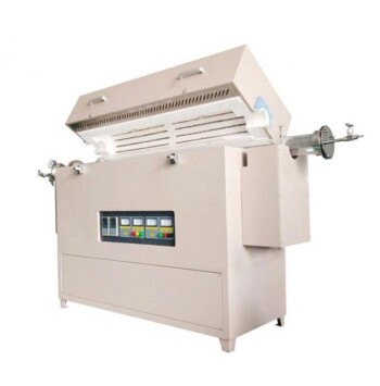
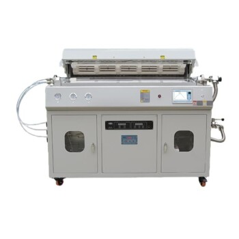
Producing a dense, transparent YSZ thin-film electrolyte demands a precise thermal sintering profile in a high-temperature laboratory furnace. The essential parameters are controlled heating rates of 5 K/min to 10 K/min, a peak soak temperature between 1380 °C and 1400 °C, and a holding time of 10 to 30 minutes. Executed correctly on a NiO-YSZ anode substrate, this recipe drives full densification without micro‑cracking or delamination.
A successful thin-film YSZ electrolyte for SOFCs results not from a single temperature number, but from a tightly choreographed thermal program. The peak temperature, the rate at which you reach it, and the dwell time together govern densification and interface integrity — the real challenge is balancing grain growth, thermal expansion mismatch, and atmosphere control throughout the entire cycle.
Why the Thermal Profile Defines Electrolyte Quality
A YSZ thin film must transform from a porous deposited layer into a gas-tight, ion-conductive ceramic. The furnace program alone controls this transformation. Deviations cause defects that ruin cell performance.
The Sintering Goal: Full Density and Transparency
Densification eliminates internal porosity. Only a fully dense electrolyte can block fuel and oxidant cross-over while maximizing oxygen-ion conductivity. The characteristic transparency of a well-sintered YSZ layer is the visible proof that light-scattering pores have vanished and grain boundaries are clean.
Thermal energy drives mass transport. At 1380 °C–1400 °C, the ceramic particles develop sufficient surface and grain-boundary diffusion to close residual voids. The thin-film geometry accelerates this relative to bulk pellets, which is why the hold time can be as short as 10–30 minutes.
Managing the Temperature Ramp
Heating rates of 5–10 K/min are the upper safe limit. Faster ramps create steep thermal gradients. These gradients produce differential expansion between the substrate, interlayer, and electrolyte, leading to cracking or delamination.
Uniform furnace temperature is non‑negotiable. Even with a moderate ramp rate, hot spots in the furnace can locally over-sinter or cause asymmetric stress. A well‑designed high‑temperature laboratory furnace with precise thermostatic control ensures the entire micro-tubular assembly experiences the same thermal history.
The Role of Atmosphere Control
Atmosphere dictates phase stability. YSZ is an oxide ion conductor; processing in air is standard. However, the NiO-YSZ substrate demands an oxidizing environment so that nickel remains oxidized during sintering (preventing metallic Ni agglomeration that would later cause shrinkage on reduction). The primary reference implies that air atmosphere, combined with the specified heating profile, supports uniform microstructural development without phase degradation.
Controlled atmosphere also prevents carbon contamination. If binder or dispersant residues from green-layer deposition remain, a ramped burnout phase at lower temperatures is essential before the high-temperature dwell. The specified 5–10 K/min ramp often includes a slow initial segment for organic removal, though the primary reference focuses on the final densification stage.
Understanding the Trade‑offs
Grain Growth vs. Density
Higher green density yields larger final grains. A dense initial layer consolidates rapidly, but excessive grain growth can weaken the film and introduce intergranular defects. The thermal profile must allow sufficient time for pore elimination while limiting grain coarsening. The 1380 °C–1400 °C window with short dwell balances these competing factors.
Going hotter is not better. While some references cite 1450 °C for hours for bulk YSZ discs, such extreme conditions on a supported thin film would cause excessive NiO coarsening in the substrate, wavy interfaces, or even melting of the gradient interlayer. Sticking to 1400 °C maximum protects substrate integrity.
Thermal Expansion Mismatch
Different layers expand and shrink at different rates. NiO-YSZ, the gradient interlayer, and YSZ electrolyte have distinct thermal expansion coefficients. A steady, moderate ramp rate and uniform temperature minimize the transient stress at interfaces. Delamination or vertical cracking is often a direct signature of a poor thermal profile, not a material failure.
Substrate Geometry Considerations
Micro-tubular cells demand extra care. Cylindrical geometries amplify thermal-gradient effects. The primary reference specifically mentions micro‑tubular NiO-YSZ substrates, so the 5–10 K/min rate and 10–30 min hold assume that furnace heating elements and insulation provide radial uniformity. Tube‑furnace setups that lack sufficient pre‑heating zones may require even slower ramps.
Making the Right Choice for Your Thin‑Film SOFC
✅ If your primary focus is achieving gas‑tight transparency:
Target 1400 °C with a 20–30 min hold at a 5 K/min ramp. This maximizes densification while the slower ramp protects the fragile green film from thermal shock.
✅ If your primary focus is preventing substrate coarsening and interface degradation:
Set the peak to 1380 °C with a 10–15 min hold and a 10 K/min ramp. This minimizes NiO grain growth inside the anode while still delivering a dense electrolyte.
✅ If your primary focus is process consistency and scaling to multiple cells:
Invest in a furnace with proven ±1 °C uniformity and multi‑zone control. Automate the ramp profile and include an organic burnout step at 300–500 °C before the main sintering ramp. This eliminates operator variability and ensures every cell sees the identical thermal history.
Your thermal processing recipe is the fingerprint on every SOFC’s performance — control it with precision, and the dense, transparent YSZ thin film will follow reliably.
Summary Table:
| Parameter | Recommended Setting | Primary Impact & Objective |
|---|---|---|
| Heating Ramp Rate | 5 K/min – 10 K/min | Prevents thermal shock, delamination, and inter-layer cracking |
| Peak Temperature | 1380 °C – 1400 °C | Drives mass diffusion for full densification without interface damage |
| Soak / Dwell Time | 10 min – 30 min | Eliminates light-scattering pores while limiting excessive grain growth |
| Process Atmosphere | Air / Controlled Oxidizing | Prevents organic contamination and retains NiO phase stability |
Achieve flawless densification and gas-tight transparency for your SOFC components with KINTEK high-temperature furnaces. Designed for demanding material research, KINTEK offers a comprehensive line of tube, muffle, atmosphere, CVD, and vacuum high-temperature furnaces featuring exceptional thermal uniformity (±1 °C) and programmable ramp controls. Whether you process planar or micro-tubular assemblies, our systems are fully customizable to meet your exact laboratory standards. Contact KINTEK today to optimize your sintering process!
Related Products
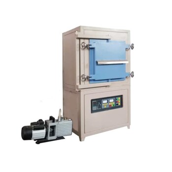
- 1700℃ Controlled Inert Nitrogen Atmosphere Furnace
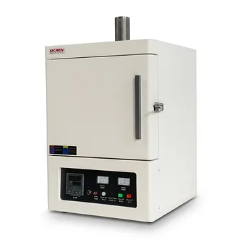
- 1200℃ Muffle Oven Furnace for Laboratory
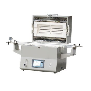
- 1400℃ High Temperature Laboratory Tube Furnace with Alumina Tube
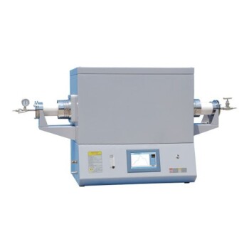
- 1700℃ High Temperature Laboratory Tube Furnace with Alumina Tube
- Laboratory Muffle Oven Furnace with Bottom Lifting
People Also Ask
- Why is thorough binder burnout necessary before sintering advanced ceramics? Ensure Peak Density & Zero Defects
- How does real-time dilatometric analysis in a controlled-atmosphere furnace optimize PZT ceramic sintering?
- How do controlled-atmosphere furnaces support polymer pyrolysis? Master SiC & Si3N4 Ceramic Conversion
- How does oxygen partial pressure control affect ceramic sintering? Master Defect Chemistry
- Why is controlled-atmosphere heating required for functional ceramics and sensors? Master Defect Engineering