Particle mean diameter is the single most critical input for calculating solid phase volume fractions in multiphase sintering models. In high-temperature furnace trials, empirical correlations directly translate the mean diameter of each raw material—such as coke breeze, sinter feed, or return fines—into its respective volume fraction. These calculated fractions define the packing structure of the bed and govern gas permeability, pressure drop, and momentum transfer throughout the thermal cycle.
While empirical formulas provide the numerical bridge between particle size and phase volume, the true role of mean diameter extends deeper: it sets the initial green packing density and the driving force for densification. Accurate volume fraction calculations allow researchers to replicate real-world sintering conditions in a laboratory furnace, ensuring that bed compaction, viscous liquid flow, and structural consolidation are faithfully simulated.
How Mean Diameter Feeds into Volume Fraction Equations
Thermal processing models do not treat a powder bed as a homogeneous block. They require the local volume fraction occupied by each solid constituent to predict transport phenomena correctly.
The Empirical Formulation for Key Components
In laboratory-scale sintering experiments, coke breeze volume fraction is often expressed as:
ε_coke = 0.153 log(d_coke) + 0.724
where d_coke is the mean particle diameter of the coke breeze. This relationship captures how coarser coke particles tend to occupy a larger volume fraction, which directly influences the bed’s reduction potential and gas flow channels.
Other iron-bearing or flux materials follow a power‑law correlation:
ε_m = 0.403 [100 d_m]^0.14
Here d_m is the mean diameter of materials like sinter feed, return sinter, fines, and mill scale. The exponent 0.14 ensures that even small changes in mean particle size appreciably shift the predicted phase volume—fine fractions pack differently, altering the contiguous network of each solid.
Why Individual Volume Fractions Are Calculated
A furnace operator or researcher rarely deals with a single-component powder. Realistic sintering charges contain multiple minerals, each with its own size distribution. By feeding the mean diameter of each component into these correlations, the model spatially resolves how much of the bed is occupied by, say, coke versus ore fines. This partitioning is the foundation for:
- Predicting gas flow resistance through the porous bed.
- Determining liquid phase distribution once low-melting components soften.
- Estimating compaction and consolidation behavior during heating.
The Deep Impact of Volume Fractions on Sintering Furnace Trials
Once volume fractions are assigned based on particle diameters, they directly influence the physical and chemical evolution inside the high-temperature furnace.
Gas Permeability and Pressure Drop
The solid phase volume fractions define the void fraction and pore network geometry. A bed with a high fraction of fine particles—hence a high computed ε_m—will exhibit reduced interparticle voids, lowering gas permeability. In sintering, that translates to a steeper pressure drop across the bed and less efficient combustion of the coke breeze. Without accurate volume fractions, the model cannot predict whether gas flow will sustain the required thermal front.
Momentum Transfer and Bed Compaction
During the initial stages of heating, unreacted solids interact via momentum exchange. The calculated volume fractions dictate how drag forces are distributed among different particle populations. A mismatch in volume fractions leads to incorrect predictions of bed settling and compaction, which then cascade into errors in heat transfer and reaction rate estimations.
Viscous Liquid Flow and Structural Consolidation
As temperature rises, some mineral phases melt and form a viscous liquid. The location and continuity of this liquid phase are directly tied to the spatial arrangement of solid volume fractions. If the coke fraction is overestimated due to an inaccurate mean diameter, the model will place too much solid carbon in the path of the liquid, unrealistically obstructing its percolation. Correct volume fractions allow the simulation of capillary-driven rearrangement and the final sinter cake strength.
The Underlying Thermodynamic and Kinetic Connections
The role of particle diameter does not stop at volume fraction calculations. The same mean diameter values govern the fundamental sintering behavior that the furnace trial aims to study.
Surface Energy and the Driving Force for Neck Growth
Smaller particles possess a much higher surface area‑to‑volume ratio and greater surface curvature. The Kelvin‑type relationship
p = p_∞ (1 + (2γV_m)/(R T r))
shows that vapor pressure and chemical potential rise dramatically as particle radius r decreases. This elevated activity creates strong gradients toward the concave menisci at interparticle necks. In a laboratory tube furnace, those gradients drive evaporation‑condensation, diffusion, and viscous flow—mechanisms that shrink porosity. Because the volume fraction calculations determine how many fine particles are present locally, they indirectly set the magnitude of these driving forces.
Densification Kinetics: Why Grain Size Appears in Every Equation
Once a stable neck network forms, the rate of densification becomes overwhelmingly sensitive to grain size. For lattice diffusion‑controlled sintering, the densification rate scales with 1/G³, while grain‑boundary diffusion‑controlled cases scale with 1/G⁴, where G is the grain diameter. The initial mean particle diameter strongly influences early‑stage grain size and thus the entire densification trajectory. A bed whose volume fractions are dominated by sub‑micron fines will sinter orders of magnitude faster than one with millimetre‑scale grains. Therefore, feeding accurate diameter values into the volume fraction equations is not a trivial bookkeeping step—it locks in the kinetic path the furnace trial will follow.
Trade‑offs and Pitfalls in Using Mean Diameter for Volume Fractions
Using a single mean diameter to represent a distribution introduces simplifications that demand careful interpretation.
The Risk of Broad Size Distributions
If a raw material has an extremely wide particle size distribution, a single mean value can hide bimodal or multimodal packing behavior. Two powders with the same mean diameter but different spans will yield the same computed volume fraction from the empirical correlation, yet their actual packing porosity and inter‑particle contacts will be vastly different. In a research furnace, this discrepancy leads to non‑uniform grain growth, uneven pore removal, and scatter in final mechanical properties.
Balancing Fine and Coarse Fractions for Phase Uniformity
A high proportion of fine particles (e.g., >83% under 63 µm) accelerates solid‑state reactions and phase transformations like mullite formation. More importantly, fine comminution prevents spatial segregation of plastic components (kaolin, montmorillonite) from non‑plastic components (quartz, albite) within the green body. If the volume fraction model only uses a coarse mean diameter, it will underestimate the fraction of finely dispersed plastic phases, predicting poor liquid‑phase distribution when, in reality, the furnace trial produces excellent microstructural homogeneity. This mismatch erodes confidence in the entire thermal processing simulation.
Grain Growth Can Render Initial Volume Fractions Irrelevant
At high furnace temperatures, holding times that are too long provoke exaggerated grain growth. Since densification rates plummet with increasing grain size (1/G³ or 1/G⁴), any sintering benefit predicted from a large initial volume fraction of fines can be completely negated. The calculated volume fractions remain static inputs, but the actual microstructure evolves dynamically. Researchers must pair accurate initial volume fraction calculations with precise thermal profiles to confine grain growth and preserve the kinetic advantage.
Making the Right Choice for Your Sintering Trial
Applying mean‑diameter‑based volume fraction correlations effectively depends on your experimental goals and the materials at hand.
- If your primary focus is replicating industrial bed permeability: Prioritize measuring the mean diameter of your coke breeze and iron ore fines as accurately as possible. Use the empirical ε correlations to tune your laboratory packing so that the pressure-drop-versus-flow curve matches plant data.
- If your primary focus is studying liquid‑phase evolution and microstructural uniformity: Commence with a powder that has a narrow size distribution and a high proportion of fines. Verify that the mean diameter you input into the ε_m equation truly reflects the dominant fine fraction, otherwise your model will underpredict the liquid connectivity.
- If your primary focus is maximizing densification kinetics in a lab furnace: Choose the finest starting powder feasible, but then use the volume fraction outputs to predict the initial green density and pore structure. Schedule heating rates that exploit the early high‑surface‑energy state before grain growth becomes the rate‑limiting factor.
- If your primary focus is comparing different raw material sources: Compute volume fractions from the mean diameter of each candidate. Run the sintering simulation and cross‑check against simple dilatometry trials in the furnace. Discrepancies often reveal an overly broad particle size distribution that the mean diameter is hiding.
Particle mean diameter is the numeric key that unlocks reliable solid‑phase volume fractions, connecting the physical powder you load into a furnace to the multiphase models that explain its sintering behavior.
Summary Table:
| Material / Parameter | Governing Relationship | Impact on Sintering Performance |
|---|---|---|
| Coke Breeze Volume Fraction | $\varepsilon_{coke} = 0.153 \log(d_{coke}) + 0.724$ | Defines gas flow channels and carbon reduction potential |
| Ore & Flux Volume Fraction | $\varepsilon_m = 0.403 [100 d_m]^{0.14}$ | Determines green bed compaction and pore structure |
| Gas Permeability & Pressure Drop | Dictated by solid void fraction (1 - $\Sigma\varepsilon$) | Governs thermal front speed and combustion efficiency |
| Densification Kinetics | Rate $\propto 1/G^3$ (lattice) or $1/G^4$ (boundary) | Controls shrinkage speed, pore removal, and final strength |
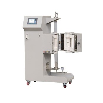
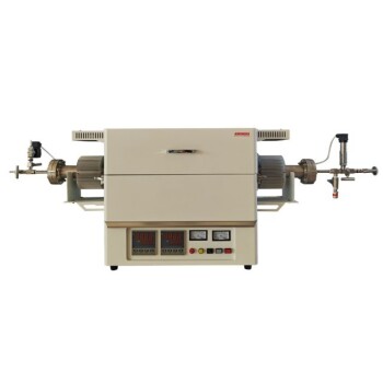
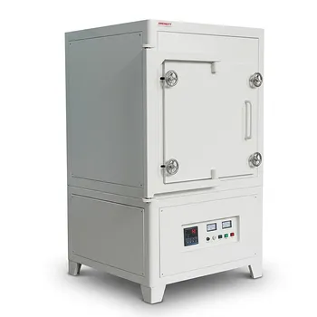
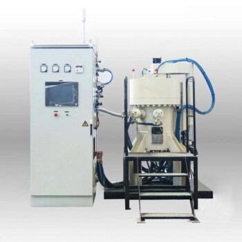
Master your high-temperature sintering trials and achieve superior microstructural control with KINTEK. As a leading provider of laboratory equipment and consumables, KINTEK offers a comprehensive selection of high-temperature furnaces—including muffle, tube, rotary, vacuum, CVD, atmosphere, dental, and induction melting furnaces—all fully customizable to meet your specific research needs. Optimize your thermal processing performance today—contact KINTEK to consult with our experts!
Related Products
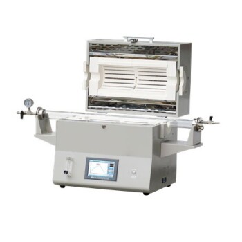
- 1400℃ High Temperature Laboratory Tube Furnace with Alumina Tube
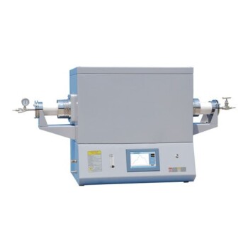
- 1700℃ High Temperature Laboratory Tube Furnace with Alumina Tube
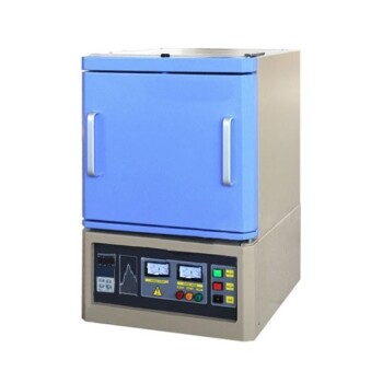
- 1800℃ High Temperature Muffle Oven Furnace for Laboratory
- 1700℃ High Temperature Muffle Oven Furnace for Laboratory
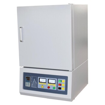
- 1200℃ Muffle Oven Furnace for Laboratory
People Also Ask
- How does zone-melting in tube furnaces synthesize bismuth micro-wires? Master Single-Crystal Thermoelectric Growth
- How do high-temperature laboratory tube furnaces ensure environmental stability? Precision Thermal Reduction Tips
- How are high-temperature laboratory tube furnaces applied in long-term vacuum homogenization heat treatments for intermetallic samples?
- How are high-temp tube furnaces used to measure diffusion coefficients per Fick's law? Master Precision Annealing
- How are high-temperature tube furnaces applied in testing ceramic-supported alloy membranes? Insights