Substrate constraint is the fundamental enemy. When a ceramic film is bonded to a rigid substrate, the furnace’s heat forces it to densify and shrink—but only in thickness, not in the plane. This confinement generates enormous biaxial tensile stress that directly drives cracking or delamination if it exceeds the film’s strength or the interface’s adhesion. The root cause is mechanical, not thermal, and it activates every time the film tries to contract laterally against an unyielding foundation.
Cracking and delamination in sol-gel and particulate ceramic films during high-temperature processing stem from substrate-imposed tensile stresses that arise when the film attempts to shrink in two dimensions but is mechanically restrained. Mitigation through furnace profiles centers on reducing the sharpest density gradients during the earliest stage of sintering, where the material is most vulnerable, while ensuring homogeneous green structures and strong interfaces.
The Hidden Engine of Failure: Constrained Shrinkage
The primary reference correctly identifies a single mechanism—constrained densification under a rigid substrate—as the core trigger for both cracking and delamination. However, the real depth of this problem only becomes clear when you examine the stress path from green body to dense ceramic.
Why a Film Under a Furnace Ramp Behaves Differently from a Bulk Part
A free-standing ceramic compact shrinks isotropically in three dimensions. In a film, the substrate locks the lateral dimensions, forcing all volume reduction into the thickness direction. This 1D contraction creates tension in the film’s plane.
The stress is not an exotic phenomenon; it is a direct consequence of the sintering potential. Particles and pores rearrange to eliminate surface area, but because the plane dimensions cannot change, the material is pulled elastically or viscoelastically, storing energy. When that stored energy exceeds the fracture toughness at a flaw or the interfacial shear strength at the substrate, failure initiates.
Critical Thickness: A Threshold with Practical Consequences
Failure is not inevitable; it has a thickness dependency.
For sol-gel derived films, the critical thickness often falls below 1 µm. The dense, nanoscale network formed during coating and drying is strong but brittle, and even modest constraint stress can drive through-thickness cracks.
For particulate coatings (slurry-deposited, micron-sized powders), the critical thickness is higher—around 50 µm—because the green packing and pore network allow for more local rearrangement and stress relaxation.
Exceeding these thresholds means that even a flawless interface will fail, either by cracking through the film or by delaminating it from the substrate.
The Amplifying Role of Pre-Existing Flaws
The primary reference notes that drying flaws can propagate under tensile stress. This is a vital extension: the actual failure stress is rarely the theoretical material strength. Instead, pores, drying cracks, agglomerates, and thickness variations act as stress concentrators.
During furnace heating, these flaws become crack initiation sites. A film that is only 10% thicker at a local defect will experience a higher local stress, and a weak interface spot will delaminate first. Therefore, the furnace profile alone cannot save a film riddled with green-state defects.
The Escalator Effect: Differential Shrinkage and Thermal Mismatch
When a film is co-fired with another layer—whether a different ceramic tape, an electrode, or a dissimilar substrate—stress becomes multidimensional and even more dangerous. This is the territory of compatibility stresses.
Why Co-Firing Demands Absolute Thermal Synchronization
Two materials that start at different green densities, particle sizes, or chemical compositions will attempt to shrink at different unconstrained rates. To stay bonded, one must stretch and the other compress, generating internal biaxial stresses that oppose the natural sintering stress.
The result is not just cracking; it is retarded densification, anisotropic microstructures with elongated pores, and warping. Precise temperature control means that the faster-shrinking layer must not outpace the slower one too early, when the pore structure is still open and vulnerable.
Thermal Expansion: The Second Hammer Blow
Even after sintering, cooling introduces further stress. A mismatch in the thermal expansion coefficient between film and substrate, or between co-fired layers, creates residual tensile stress upon cooling. If this is superimposed on an already damaged microstructure, cracks can nucleate or propagate long after the furnace has cooled. The furnace profile must therefore manage both heating and cooling ramps with equal rigor.
The Aggravators: Dewetting and Debinding Defects
Constrained sintering and differential shrinkage are the primary mechanisms, but two additional failure modes can destroy an otherwise well-processed film during furnace dwells.
Morphological Instability and Grain Boundary Grooving
For polycrystalline thin films (like yttria-stabilized zirconia), prolonged high-temperature exposure can trigger dewetting. Surface tension drives grooving where grain boundaries intersect the film surface. If the grain size relative to film thickness exceeds a critical ratio (e.g., grain diameter > ~7× film thickness for a 120° dihedral angle), the groove penetrates to the substrate, breaking the film into isolated islands.
Mitigation lies in furnace profiles that limit the total time at peak temperature, thereby preventing runaway grain growth. This is a timing problem, not a ramp-rate problem.
The Hidden Dangers of Binder Burnout
Before sintering, most ceramic films contain organic binders. Thermal debinding produces volatile gases that must escape through the porous network. If the heating rate is too aggressive, gas pressure inside pores can cause microcracks, voids, or delamination before the sintering stresses ever become dominant.
A furnace profile that ramps too quickly during the 200–500°C range can wreak havoc that no later careful sintering ramp can fix. Sufficiently slow heating and excellent temperature uniformity across the furnace load are essential.
How Furnace Profiles Act as the First Line of Defense
The furnace profile is not a cure-all, but it is the most powerful operational lever. The key is to understand when the film is most fragile and to reduce the driving force for stress at exactly those moments.
The Critical Early-Stage Ramp
The initial stage of sintering, when relative density is low (e.g., <65–70%), is when the material has the least capacity to resist tensile stress. Particles are only just bonding; the network is fragile.
Applying a low heating rate during this phase—often a prolonged soak or a ramp of just 1–2°C/min—allows the pore structure to coarsen and the neck geometry to evolve without building up high constraint tension. Once the density passes a threshold, the film can withstand faster heating because the solid network is more continuous and stress relaxation mechanisms improve.
Thorough Drying and Debinding: A Pre-Furnace Requirement That the Profile Protects
The primary reference emphasizes thorough green-state drying. This is not strictly part of the high-temperature furnace profile, but the profile must include a controlled drying/debinding segment if solvents and organics are still present.
A profile that starts with an extended low-temperature plateau (e.g., 100–150°C for water removal, followed by slow ramps through the binder decomposition range) ensures that volatile escape does not disrupt particle packing. Once the green body is dry and binder-free, the furnace can transition to the sintering ramp without a legacy of internal damage.
Maximizing Green Density and Interface Adhesion: Profile-Independent Enablers
These are process steps before the furnace, but they define the furnace’s success opportunity. A film with a high and uniform green packing density will shrink less total volume, generating lower constraint stress. A strong interfacial bond can withstand higher shear stresses before delamination.
A furnace profile can only work with the microstructure it is given. If green density is poor or the substrate surface is contaminated, even the most gentle furnace ramp will fail.
Cooling Ramps and Homogenization
After densification, residual stress from differential thermal contraction can crack a film that survived sintering. The furnace profile must therefore include a controlled cooling stage, often with a hold at an intermediate temperature to allow stress relaxation, and a ramp slow enough to avoid sharp thermal gradients across the component.
Understanding the Trade-offs
No mitigation strategy is without downsides. An honest advisor must highlight the practical constraints.
Extended processing time. A very slow initial heating rate and multiple dwells can make a 4-hour cycle into a 12-hour one. For production, this reduces throughput and increases energy costs per part. The optimal profile balances defect elimination with economic reality.
Thresholds still exist. Even with the perfect profile, a sol-gel film >1 µm or a particulate film >50 µm may still crack because the total shrinkage strain energy accumulates beyond what the material can survive. Furnace optimization cannot defeat physics; it only pushes the boundary slightly.
Transient liquid phases—a double-edged sword. Introducing additives that form a transient liquid at temperature (mentioned in supplementary references) can relax stresses and aid densification. However, they may leave residual glass phases at grain boundaries that degrade high-temperature mechanical or electrical properties. The furnace profile must then account for liquid formation and its subsequent evaporation or crystallization.
Dewetting is a dwell-time risk. A profile designed for gentle sintering may inadvertently extend the time at temperature, allowing grain growth and film rupture in polycrystalline systems. Operators must offset slow ramps with a shorter peak dwell to avoid crossing the grain-size-to-thickness threshold.
Furnace uniformity is an overlooked variable. Even a perfectly programmed cycle will cause defects if the furnace has cold spots or poor temperature distribution. The profile must be tuned to the actual part temperature, not just the setpoint, which may require calibration trials.
Making the Right Choice for Your Goal
Your specific film system and performance requirements determine which furnace strategies to prioritize. Align your profile with the dominant risk.
- If your primary focus is preventing cracks in submicron sol-gel films: Keep the final thickness below 1 µm, use a prolonged ramp from drying completion through the early sintering stage (e.g., 1°C/min up to ~700°C), and ensure the substrate is chemically bonded or activated for maximum adhesion. Then, carefully manage cooling to avoid thermal expansion mismatch stresses.
- If your primary focus is processing thick particulate coatings (tens of microns): Maximize green packing density through optimized dispersion and deposition, then use a furnace profile with an extended debinding hold (slow ramp through 250–450°C) and a moderate initial sintering ramp. Do not rely on thickness reduction alone; the interface must be clean and potentially modified with a bonding layer.
- If your primary focus is co-firing multilayered devices with dissimilar materials: First, match the sintering onset temperatures and shrinkage rates by adjusting particle size and green density of each layer. Then, program a furnace profile with plateau holds at temperatures where one layer starts to densify significantly, allowing differential stress to relax before ramping further. Post-sinter cooling must be slow and uniform.
- If your primary focus is maintaining continuous polycrystalline films without dewetting: Limit the peak temperature dwell time to the minimum required for densification, and consider a two-step profile that promotes densification at a lower temperature before a short grain-growth control step. Monitor the grain-size-to-thickness ratio and stay well below the critical threshold.
A furnace is not just a heat source; it is a stress management tool. By slowing down at the moments your film is most fragile and giving it the microstructural quality it needs to survive, you transform a process prone to catastrophic failure into a predictable, repeatable pathway to crack-free ceramic coatings.
Summary Table:
| Film System | Primary Failure Mechanism | Critical Thickness | Recommended Furnace Strategy |
|---|---|---|---|
| Sol-Gel Films | Biaxial tensile stress from 1D shrinkage | < 1 µm | Low early-stage ramp (1–2°C/min) & controlled cooling |
| Particulate Coatings | Gas pressure from debinding & flaw propagation | ~50 µm | Extended 200–500°C debinding hold & uniform green density |
| Co-Fired Multilayers | Differential thermal expansion & shrinkage mismatch | Dynamic | Synchronized multi-stage heating ramps & intermediate soak holds |
Eliminate Film Defects with Precision Thermal Control
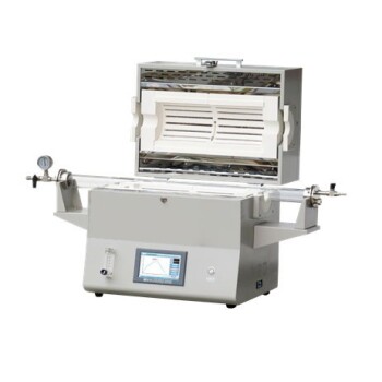
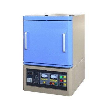
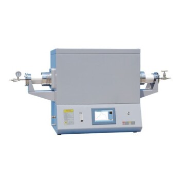
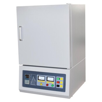
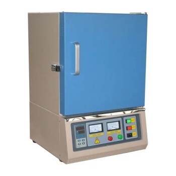
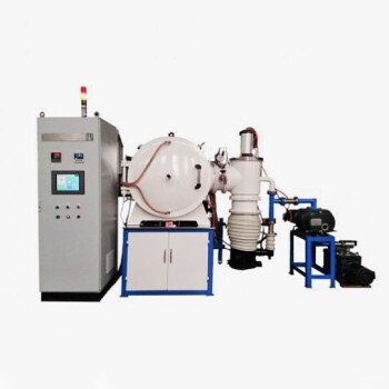
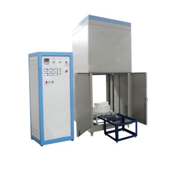
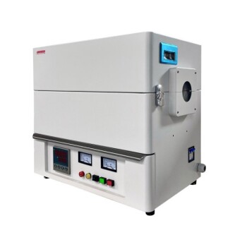
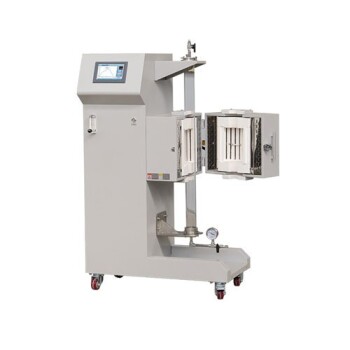
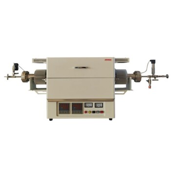
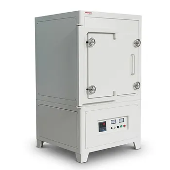
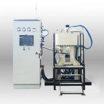
Struggling with cracking, warping, or delamination during ceramic processing? KINTEK specializes in advanced laboratory equipment and fully customizable high-temperature furnaces—including muffle, tube, rotary, vacuum, atmosphere, CVD, and dental furnaces—built to deliver exceptional temperature uniformity and precise ramp control.
Whether you are developing submicron sol-gel coatings or scaling complex multilayer ceramics, our high-precision thermal systems empower you to eliminate internal stress and maximize yield. Contact KINTEK today to consult with our engineering experts and find the ideal custom furnace solution for your lab!
Related Products
- 1400℃ High Temperature Laboratory Tube Furnace with Alumina Tube
- 1800℃ High Temperature Muffle Oven Furnace for Laboratory
- 1700℃ High Temperature Laboratory Tube Furnace with Alumina Tube
- 1700℃ High Temperature Muffle Oven Furnace for Laboratory
- 1200℃ Muffle Oven Furnace for Laboratory
People Also Ask
- How does zone-melting in tube furnaces synthesize bismuth micro-wires? Master Single-Crystal Thermoelectric Growth
- How do high-temperature laboratory tube furnaces ensure environmental stability? Precision Thermal Reduction Tips
- How are high-temp tube furnaces used to measure diffusion coefficients per Fick's law? Master Precision Annealing
- How are high-temperature laboratory tube furnaces applied in long-term vacuum homogenization heat treatments for intermetallic samples?
- How are high-temperature tube furnaces applied in testing ceramic-supported alloy membranes? Insights