To prevent cracking, blistering, and slumping, your debinding heating schedule hinges on balancing gas generation with gas escape. The critical parameters are ramp rates, isothermal hold temperatures and durations, and furnace atmosphere control, all tailored to the specific decomposition behavior of your binder system. By aligning the thermal profile with thermogravimetric analysis (TGA) data and the three distinct debinding stages—softening, rapid degradation, and carbon burnout—you create a safe pathway for volatiles to leave without building internal pressure that disrupts the ceramic microstructure.
A defect-free debinding schedule is not a single recipe; it’s a process-specific strategy that matches heating steps to the binder’s critical decomposition windows. The key is to keep internal gas pressure below the green body’s strength limit by slowing down exactly where TGA shows the highest weight-loss rates, and to hold long enough at the right temperatures to open interconnected pores early.
The Root Cause of Debinding Defects
Two Simultaneous Stress Sources
Binder removal failures arise from gas pressure gradients and thermal stresses. When volatile decomposition products evolve faster than they can diffuse through the binder-filled pores, internal pressure spikes, causing microcracks or blisters. At the same time, steep temperature gradients across the part create uneven thermal expansion, leading to warping or distortion. Your heating schedule must address both.
The Critical Role of Pore Network Formation
In the early stages, pores are clogged with binder, offering high diffusion resistance. Only after a continuous, open pore network develops can gases escape freely. The schedule must be slowest before this network exists. Once interconnected porosity is established, ramp rates can safely increase without risking pressure buildup.
The Three Thermal Debinding Stages and Their Parameters
Stage 1: Low-Temperature Softening (<200°C)
Low molecular weight additives, plasticizers, and residual solvents vaporize. Because the pore network is still binder-blocked, these early volatiles can easily form bubbles or microvoids if heated too quickly. The primary control parameter here is a very slow ramp (often <1°C/min) and, if needed, a short isothermal hold to allow gentle outgassing without rapid expansion.
Stage 2: Rapid Thermal Degradation (200–300°C)
The main binder polymers thermally crack into volatile oligomers. Capillary forces redistribute molten binder, creating nonplanar interfaces that shorten diffusion paths. This stage is the highest risk zone for pressure-related defects. Your schedule must include reduced ramp rates and strategic isothermal holds directly within the peak mass-loss temperature window identified by TGA. The goal is to keep the gas generation rate at or below the maximum safe weight-loss rate the part can sustain.
Stage 3: Carbon Elimination & Final Burnout (300–600°C+)
Residual high-molecular-weight species decompose slowly through the now-open porosity. While heating can be faster, you still need to reach temperatures above 600°C (often under controlled atmosphere) to thoroughly eliminate carbon residues. Incomplete burnout here can later impede sintering density. The key parameter is a sufficient high-temperature hold with proper air or gas flow to carry away final volatiles.
How TGA Directly Defines Your Heating Schedule
Identifying Peak Temperature Windows
Thermogravimetric analysis (TGA) measures mass loss versus temperature under controlled heating. The derivative curve (DTG) pinpoints the exact temperatures where decomposition accelerates. These become your critical debinding zones—typically between 200°C and 400°C. Your schedule must apply slow ramps and holds across these narrow ranges.
Setting a Maximum Allowable Weight-Loss Rate
The part’s geometry and green strength dictate a maximum weight-loss-per-unit-time that avoids cracking. By running TGA at different heating rates, you determine the ramp-rate ceiling for each temperature segment. The furnace program then never exceeds that rate, using holds to “pause” the process if needed until the binder has time to diffuse out.
Designing the Multi-Stage Heating Profile
Ramp Rate Control
Start the cycle with a slow initial ramp (0.2–1°C/min) from room temperature to just past the softening stage. In the rapid degradation zone, ramp rates may need to dip even lower—sometimes 0.1°C/min or less—exactly where DTG shows the sharpest mass loss. After open porosity forms, ramp rates can typically be increased to 2–5°C/min for the remainder of the cycle.
Strategic Isothermal Holds
Holds are placed just before and within peak decomposition windows. A hold just below the rapid-degradation onset temperature equilibrates the part thermally and begins opening partial pore channels. A hold in the middle of the mass-loss peak allows built-up gas pressure to dissipate. Duration is based on part thickness and TGA data: hours for thick sections, often tens of minutes for thin samples.
Accelerating After Open Porosity
Once the binder has melted and redistributed to create continuous pore channels—usually after the main degradation hold—internal diffusion resistance drops dramatically. This is the signal to ramp up the furnace rate and save cycle time without sacrificing quality. Premature acceleration before pore opening is a primary cause of blistering.
Furnace Atmosphere and Uniformity: The Hidden Parameters
Atmosphere Circulation and Composition
Stagnant gas blankets can cause localized concentration buildup, effectively blocking further outgas diffusion. The furnace must provide active atmosphere circulation—either air for oxidative debinding or controlled inert gas flow—to sweep away volatiles uniformly. In carbon elimination stages, oxygen or water vapor levels directly affect burnout efficiency and must be precisely regulated.
Temperature Uniformity and Gradient Control
All the careful ramp profiling is useless if the furnace has hot or cold spots. A high-thermal-uniformity furnace (±5°C or better) ensures every section of each part follows the intended temperature-time profile, avoiding internal thermal stresses that can initiate cracks. Proper load placement and using setters to support parts also minimize gradient-driven distortion.
Understanding the Trade-offs
Overly Conservative Heating
Extremely slow ramps and long holds eliminate gas-pressure defects but risk incomplete binder removal if temperatures never reach the carbon burnout range. This leaves residual organics that cause bloating or poor sintering later. The schedule must extend sufficiently high in temperature, not just be slow.
Ignoring the Binder System Design
Heating schedules become far easier when you use multi-component binder systems with staged removal temperatures. Low-temperature components volatilize first, creating early pore channels for the later, heavier binders. Without this, a single-component binder can demand impossibly slow rates. The furnace schedule and binder formulation are interdependent.
Thermal Stresses from Rapid Cooling
Defects aren’t only about heating. After debinding, cooling too quickly can shock the delicate green body, causing cracks. The cooling rate should be controlled, especially through the glass transition or phase-change regions, to let the part contract uniformly before final sintering.
Making the Right Choice for Your Process
- If your primary focus is defect elimination: Derive a TGA-informed profile with slow ramps (<1°C/min) in the 200–400°C window, insert multiple isothermal holds even for small parts, and ensure maximum furnace airflow uniformity. Sacrifice cycle time for absolute microstructural integrity.
- If you need to balance throughput and quality: Leverage a multi-component binder system to open pores early, then optimize hold durations by testing the shortest safe times that still prevent cracking. Use validated TGA weight-loss-rate ceilings to accelerate ramping exactly where the pore network opens.
- If your parts are thick or geometrically complex: Extend all holds and reduce ramp rates further to account for longer diffusion paths. Prioritize furnace temperature uniformity to the ±3°C range, and consider supporting the parts to prevent slumping during binder softening.
Every successful debinding schedule is a data-driven compromise between thermodynamic necessity and furnace capability—master the critical temperature windows and you master the part quality.
Summary Table:
| Debinding Stage | Temp Window (°C) | Recommended Ramp Rate | Key Strategy & Parameter Control |
|---|---|---|---|
| 1. Low-Temp Softening | < 200°C | Very slow (< 1.0°C/min) | Prevent bubble formation while pores are still clogged; allow gentle outgassing. |
| 2. Rapid Degradation | 200°C – 300°C | Ultra-slow (0.1–0.5°C/min) | Highest risk zone; align ramp rates and holds with peak TGA mass-loss window. |
| 3. Carbon Burnout | 300°C – 600°C+ | Accelerated (2.0–5.0°C/min) | Ensure continuous gas flow and temperature >600°C to fully eliminate residual carbon. |
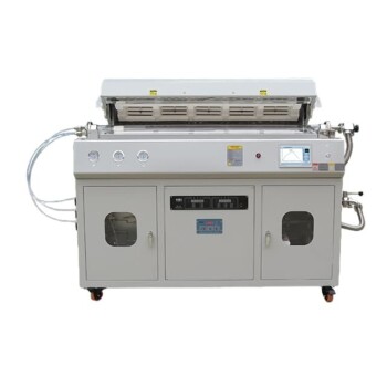
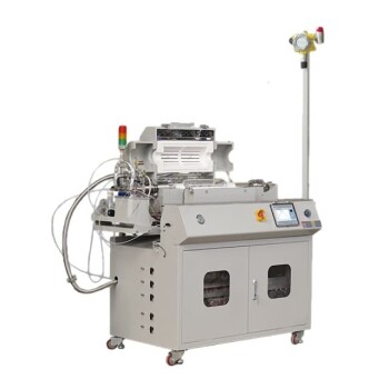
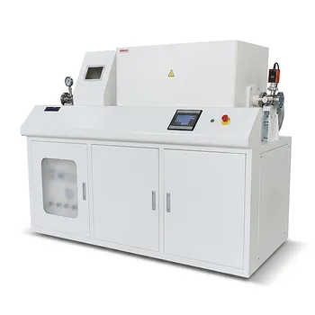
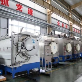
Eliminate cracking, blistering, and distortion in your ceramic components with high-precision thermal processing solutions from KINTEK. Specializing in advanced laboratory equipment and high-temperature furnaces—including atmosphere, muffle, tube, vacuum, CVD, and induction melting systems—we deliver superior temperature uniformity (±5°C or tighter) and controlled atmosphere circulation to ensure safe, repeatable debinding cycles.
Whether you require a standard unit or a fully customizable high-temperature furnace tailored to your unique binder system, our technical experts are ready to optimize your production yield. Contact KINTEK today to upgrade your thermal processing capabilities!
Related Products
- High Temperature Muffle Oven Furnace for Laboratory Debinding and Pre Sintering
- Laboratory Quartz Tube Furnace RTP Heating Tubular Furnace
- Multi Heating Zones CVD Tube Furnace Machine for Chemical Vapor Deposition Equipment
- Custom Made Versatile CVD Tube Furnace Chemical Vapor Deposition CVD Equipment Machine
- Slide PECVD Tube Furnace with Liquid Gasifier PECVD Machine
People Also Ask
- What thermal phenomena occur during polymer binder burnout in ceramic green bodies? Lab Furnace Guide
- Why is controlled heat treatment in a muffle furnace necessary for calcined clay? Achieve Optimal Pozzolanic Activity
- What role does a high-temperature muffle furnace play in STFO synthesis? Achieve Pure Perovskite Results
- How does a high-temperature muffle furnace facilitate the formation of LaNbxAl1−xO3+δ perovskite structures? Key Roles
- What role does a high-temperature muffle furnace play in the multi-stage synthesis of Li0.5MnFe1.5O4? Key to Pure Spinel