Your debinding schedule must prioritize patience over speed during the earliest phase of the cycle. Start with a heating rate below 1°C/min and incorporate carefully placed isothermal holds to give volatile gases a safe path out of the part. Only after an interconnected network of open pores has formed—allowing decomposition products to escape freely—can you safely accelerate the ramp for the rest of the thermal profile.
Designing a defect-free high-temperature debinding schedule is a balance between the rate at which volatile gases are generated and the rate at which they can escape through the developing pore network. Slow initial ramps and strategic holds during the binder’s peak decomposition windows are not conservative choices; they are essential physical requirements to prevent internal pressure from blistering, cracking, or distorting the green body.
Why Defects Occur During Debinding
The root cause of nearly every debinding flaw—blisters, warping, microcracks, or catastrophic bursting—is gas pressure exceeding the green body’s strength. When organic binders decompose, they transform into volatile species that must travel through a network of binder-filled pores to reach the surface. If the furnace heats too aggressively, gas generation outpaces diffusion, and internal pressure rises until the ceramic fails.
The Role of the Pore Network
In the green state, pores are saturated with binder. This creates a huge diffusion resistance. As debinding progresses, capillary forces redistribute molten binder, creating nonplanar interfaces that shorten diffusion distances. The moment an open, interconnected pore network emerges is the turning point: gas can escape with far less resistance, and the heating rate can increase without risk.
How Rapid Heating Creates Flaws
A fast thermal ramp spikes the rate of decomposition before any porosity has opened. Volatile molecules accumulate, form bubbles, and push the soft ceramic matrix apart. This can manifest as internal cracks that only appear during sintering or as immediate surface blistering. Even subtle overheating can leave a part weakened and prone to later failure.
The Three Critical Stages of Binder Burnout
High-temperature debinding follows a predictable sequence of physical and chemical events. Your furnace schedule must be tailored to each stage, never relying on a single linear ramp.
1. Low-Temperature Softening (Below 200°C)
Low molecular weight additives, plasticizers, and residual solvents vaporize. The gases must diffuse through binder-filled pores, which is extremely slow. A ramp rate of 0.5–1°C/min is typical here, often culminating in an isothermal hold around 100–120°C to allow absorbed water and light volatiles to escape without building pressure. Moving too quickly at this stage almost guarantees bubble formation.
2. Rapid Thermal Degradation (200°C–300°C)
This is the most dangerous zone. Main binder polymers break down violently into volatile oligomers and monomers. The generation rate of gas spikes. Your schedule must embed at least one substantial isothermal hold within this window—often at the temperature identified by thermogravimetric analysis (TGA) as the peak weight-loss rate. The hold duration is determined by how long it takes for the part to degas at a rate the microstructure can tolerate. Once an interconnected pore network forms during this stage, the danger passes.
3. Carbon Elimination and Final Burnout (300°C–600°C+)
Residual high molecular weight species decompose slowly, and carbon residues oxidize. Because porosity is now largely open, the furnace can ramp more aggressively—often 2–5°C/min or higher—toward a final hold at 550–600°C to ensure clean burnout. For clay-based ceramics, an additional dwell near 550°C is critical to safely release water from kaolinite dehydroxylation without cracking.
Designing the Heating Schedule: A Data-Driven Approach
A generic schedule is a gamble. The most reliable method uses thermogravimetric analysis (TGA) on the green body to map exactly how the binder decomposes as temperature rises. This reveals the maximum allowable weight-loss rate and the temperature windows where gas evolution peaks.
Translating TGA Data into a Furnace Program
From the TGA curve, you identify the critical temperature zones where weight loss accelerates. In those zones, you reduce the ramp rate below the safe threshold (often <1°C/min) and insert isothermal holds that last until the rate of mass loss naturally subsides. A typical multi-stage profile for a binder-containing ceramic might include:
- 40–100°C hold: Removes absorbed water and light solvents.
- 200–250°C hold: Accommodates the initial burst of polymer degradation.
- 300°C hold: Addresses any secondary decomposition peaks.
- 500–550°C hold (for clay-based bodies): Allows dehydroxylation without pressure spikes.
Outside these zones, the ramp can accelerate, dramatically shortening total cycle time without compromising part integrity.
The Role of Multi-Component Binder Systems
When a single binder is used, all decomposition happens in one narrow temperature range, forcing an extremely slow, single hold. Multi-component binder systems with staged degradation temperatures are a strategic advantage. A low-temperature component can vaporize early, creating interconnected pore channels before the main polymer decomposes. This early porosity lowers diffusion resistance for the later, more aggressive outgassing steps, enabling faster overall cycles.
Common Pitfalls and Trade-offs in Schedule Optimization
There is no perfect universal schedule. Practical constraints force trade-offs between defect risk and production throughput.
Over-Conservative vs. Over-Aggressive Profiles
A schedule that is unnecessarily slow wastes energy and furnace time without improving part quality. Conversely, trimming holds too aggressively to increase output inevitably raises defect rates—sometimes visibly, sometimes as latent flaws that emerge only after sintering. The sweet spot is the fastest program that keeps the maximum internal gas pressure consistently below the green body’s tensile strength.
Ignoring Furnace Atmosphere Uniformity
A furnace with poor thermal uniformity can create hot spots where local decomposition outpaces the bulk. Even a well-designed heating profile fails if parts see a 20°C temperature spread. Atmosphere circulation and careful part placement are part of the schedule design. Oxidizing atmospheres can accelerate carbon burnout above 500°C, while inert gases may be needed to prevent oxidation of sensitive phases.
Clay-Specific Chemistry
If your ceramic contains clay minerals, neglecting the dehydroxylation hold at 550°C is a common mistake. The release of structural water is as destructive as binder degradation. Incorporating that hold into the post-debinding ramp is non-negotiable for crack-free ware.
How to Apply This to Your Process
The following goal-based recommendations will help you configure a heating schedule that matches your production priorities without compromising part integrity.
- If your primary focus is achieving zero visible and latent defects: Start with a TGA-derived schedule, add an extra 30-minute hold within every major weight-loss window, and keep all ramp rates in the critical zone below 0.5°C/min.
- If your primary focus is maximizing throughput without scrapping parts: Validate a baseline slow schedule first, then incrementally reduce hold times by 10–15% while inspecting for microcracks with a dye penetrant until you find the failure threshold.
- If you work with clay-based ceramics: Always insert dedicated holds at 100°C (water), 250°C (organics), and 550°C (dehydroxylation) regardless of binder TGA data, as these are fixed chemical events.
- If you can influence binder formulation: Adopt a multi-component system with an early-burnout phase to create escape channels at lower temperatures, which will allow a 20–40% reduction in total debinding hold time.
A meticulously programmed high-temperature furnace schedule turns the most vulnerable part of ceramic processing into a predictable, repeatable step. Respect the gas transport physics, and your green bodies will enter the sintering zone with their microstructure intact and ready for densification.
Summary Table:
| Debinding Stage | Temperature Range | Recommended Heating Strategy | Key Objective & Defect Prevention |
|---|---|---|---|
| 1. Softening & Volatiles | < 200°C | Ramp 0.5–1°C/min; Hold @ 100–120°C | Evaporate water & light solvents without bubble formation |
| 2. Polymer Degradation | 200°C–300°C | Slow ramp (<1°C/min) + TGA-driven holds | Form interconnected open pores; prevent pressure buildup |
| 3. Final Carbon Burnout | 300°C–600°C+ | Ramp 2–5°C/min; Hold @ 550°C (clay bodies) | Eliminate residual carbon & achieve complete dehydroxylation |
Eliminate debinding flaws and optimize your ceramic manufacturing with high-precision thermal equipment from KINTEK. Precise temperature control and atmosphere uniformity are essential to safely forming open pore networks without cracking or warping your green bodies.
KINTEK specializes in comprehensive laboratory equipment and consumables, offering a complete range of customizable high-temperature furnaces—including muffle, tube, rotary, vacuum, CVD, atmosphere, dental, and induction melting furnaces—tailored to your exact material needs.
Ready to achieve flawless sintering results? Contact KINTEK today to speak with our furnace experts!
Related Products
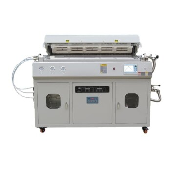
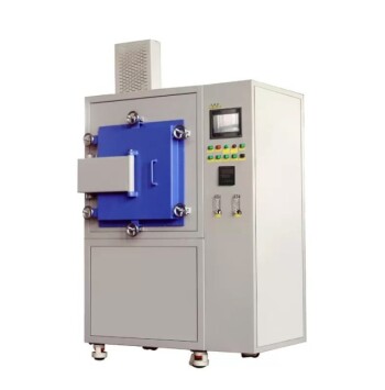
- High Temperature Muffle Oven Furnace for Laboratory Debinding and Pre Sintering
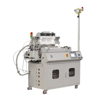
- 1400℃ High Temperature Laboratory Tube Furnace with Alumina Tube
- 1700℃ High Temperature Laboratory Tube Furnace with Alumina Tube
- 1700℃ Controlled Inert Nitrogen Atmosphere Furnace
- 1800℃ High Temperature Muffle Oven Furnace for Laboratory
People Also Ask
- What thermal phenomena occur during polymer binder burnout in ceramic green bodies? Lab Furnace Guide
- Why is controlled heat treatment in a muffle furnace necessary for calcined clay? Achieve Optimal Pozzolanic Activity
- What role does a high-temperature muffle furnace play in STFO synthesis? Achieve Pure Perovskite Results
- How does a high-temperature muffle furnace facilitate the formation of LaNbxAl1−xO3+δ perovskite structures? Key Roles
- What role does a high-temperature muffle furnace play in the multi-stage synthesis of Li0.5MnFe1.5O4? Key to Pure Spinel