First and foremost, replacing a Silicon Carbide (SiC) resistor requires a strict sequence of safety and handling procedures. The process involves completely de-energizing the equipment, carefully releasing the existing component's mechanical and electrical connections, and then installing the new resistor at a controlled speed to prevent thermal shock, which can instantly fracture the new part.
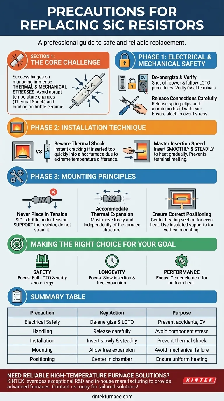
The core challenge in replacing a SiC resistor is not the mechanical swap itself, but managing the immense thermal and mechanical stresses involved. Success hinges on preventing both abrupt temperature changes (thermal shock) and any form of binding or tension on the brittle ceramic material.
The Foundation: Electrical and Mechanical Safety
Before you touch the component, you must ensure the system is completely safe. This is a non-negotiable first step.
H3: De-energize and Verify
Always shut off all power to the furnace or heating equipment. Follow standard Lockout/Tagout (LOTO) procedures to ensure the circuit cannot be accidentally re-energized while you are working.
Use a properly rated multimeter to verify that no voltage is present at the resistor terminals before proceeding.
H3: Release the Connections
Carefully release the spring clips and aluminum braid that form the electrical connections. These components are designed to provide firm contact while allowing for thermal expansion, so handle them with care.
Ensure there is enough slack to remove the old resistor without putting stress on the terminal connections or the furnace structure.
The Critical Step: Installation Technique
The way you install the new resistor is the single most important factor in preventing its immediate failure. SiC is a ceramic and is highly susceptible to cracking if not handled correctly.
H3: The Dangers of Thermal Shock
A new SiC resistor at room temperature will crack instantly if it is inserted too quickly into a hot furnace chamber. This failure, known as thermal shock, occurs because of the extreme temperature difference across the material.
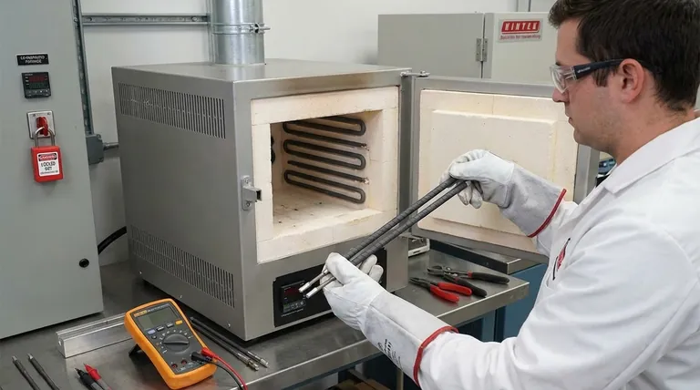
H3: Mastering the Insertion Speed
The new resistor must be inserted smoothly and steadily. This controlled speed allows the element to heat up gradually as it enters the hot zone, minimizing thermal stress.
A slow, continuous motion also prevents the aluminum terminals from melting due to prolonged exposure at the furnace opening.
Avoiding Premature Failure: Key Mounting Principles
Incorrect mounting is a leading cause of premature SiC resistor failure. The goal is to hold the resistor securely while allowing it complete freedom to expand and contract.
H3: Never Place Resistors in Tension
SiC elements are extremely strong under compression but brittle and weak under tension. The mounting system must not pull on the resistor. It should be supported, not strained.
H3: Accommodate Thermal Expansion
As the resistor and the furnace heat up, they expand. The resistor must be able to move freely and independently of the furnace structure. Any binding will create mechanical stress that will eventually fracture the element.
H3: Ensure Correct Positioning
Whether mounted horizontally or vertically, the resistor's heating section should be centered within the furnace chamber. This ensures even heat distribution and prevents the element from touching the furnace walls or insulation, which could cause a hot spot and lead to failure.
If mounting vertically, use electrically insulated supports to hold the bottom of the element.
Making the Right Choice for Your Goal
- If your primary focus is safety: Always implement a full Lockout/Tagout procedure and verify zero energy before beginning any work.
- If your primary focus is component longevity: Insert the new resistor slowly and steadily to prevent thermal shock, and ensure its mounting allows for free thermal expansion.
- If your primary focus is optimal furnace performance: Center the heating element within the chamber to guarantee uniform heat radiation and system efficiency.
By treating the resistor as a sensitive ceramic component, you ensure a safe replacement and reliable, long-term operation.
Summary Table:
| Precaution | Key Action | Purpose |
|---|---|---|
| Electrical Safety | De-energize and verify with LOTO | Prevent accidents and ensure no voltage |
| Handling | Release connections carefully | Avoid stress on brittle components |
| Installation | Insert slowly and steadily | Prevent thermal shock and cracking |
| Mounting | Allow free thermal expansion | Avoid mechanical stress and failure |
| Positioning | Center in furnace chamber | Ensure uniform heating and efficiency |
Need reliable high-temperature furnace solutions? KINTEK leverages exceptional R&D and in-house manufacturing to provide advanced furnaces like Muffle, Tube, Rotary, Vacuum & Atmosphere, and CVD/PECVD Systems. Our strong deep customization capability ensures we meet your unique experimental needs. Contact us today to enhance your lab's safety and performance with tailored solutions!
Visual Guide
Related Products
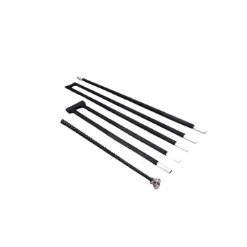
- Silicon Carbide SiC Thermal Heating Elements for Electric Furnace
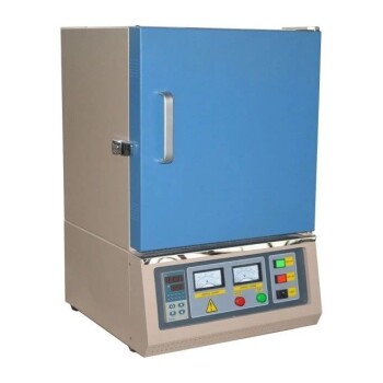
- 1400℃ Muffle Oven Furnace for Laboratory
People Also Ask
- What are some common types of silicon carbide heating elements? Explore Shapes, Coatings, and High-Temp Performance
- What are the advantages of using silicon carbide heating elements in industrial furnaces? Boost Efficiency and Durability
- How do silicon carbide heating elements enhance the heat treatment of alloys? Achieve Superior Temperature Control
- How do the different types of silicon carbide heating elements compare in terms of applications? Find the Best Fit for Your High-Temp Needs
- What are the operational advantages of silicon carbide heating elements? Achieve High-Temp Efficiency and Durability