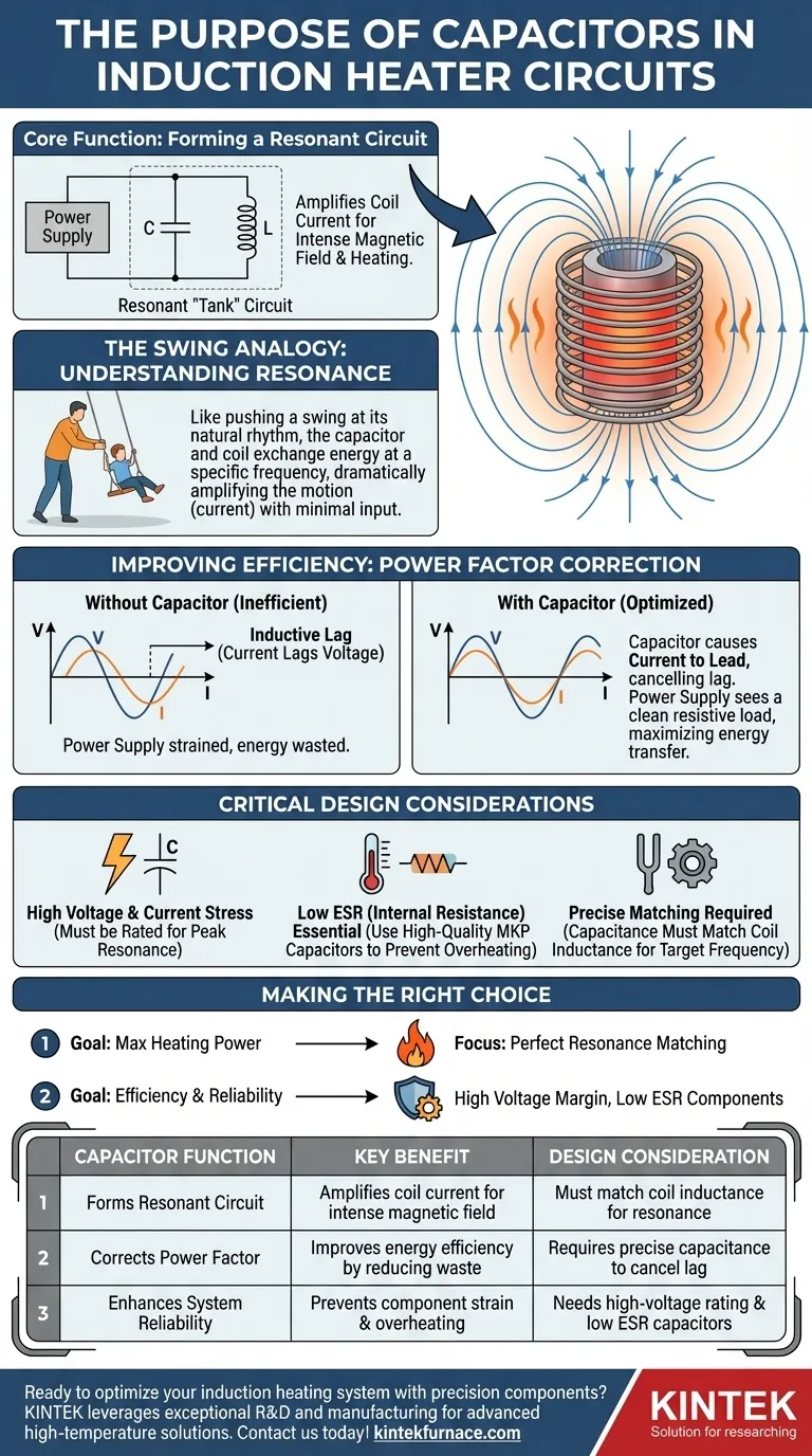
In an induction heater, the capacitor's primary purpose is to form a resonant circuit with the induction coil. This resonance is the key mechanism that amplifies the current in the coil, generating the intense, high-frequency magnetic field required to heat a metal workpiece efficiently. The capacitor also improves the circuit's power factor, ensuring the power supply's energy is used for heating rather than being wasted.
An induction coil by itself is a very inefficient load for a power supply. The capacitor transforms this inefficiency by creating a resonant "tank" circuit, which acts like a flywheel for electrical energy, dramatically multiplying the coil's heating power for a minimal input.

The Core Principle: The Resonant Tank Circuit
To understand the capacitor's role, you must first understand that the work coil is an inductor. The magic of induction heating happens when this inductor is paired with a capacitor to create a resonant circuit.
What is a Resonant Circuit?
A resonant circuit, often called an LC or "tank" circuit, is formed by an inductor (L) and a capacitor (C).
Think of it like pushing a child on a swing. The inductor (coil) and capacitor pass energy back and forth between each other at a specific natural frequency, just as a swing has a natural rhythm.
If you push the swing at precisely the right moment in its cycle (its resonant frequency), each push adds to its momentum, and it swings much higher with very little effort.
Why Resonance is Essential for Induction Heating
The work coil on its own is an inductor, which naturally resists changes in current. Driving it directly is like trying to push that swing erratically—you waste a lot of energy and get very little movement.
To generate enough heat, you need a very large, rapidly changing current in the coil to create a powerful magnetic field. Achieving this with brute force would require an enormous, inefficient power supply.
How Capacitors Create Amplification
By adding the right capacitor in parallel with the coil, you create a resonant tank circuit.
When the power supply "pushes" this circuit at its natural resonant frequency, the energy sloshes between the capacitor's electric field and the coil's magnetic field.
This resonant action causes the current and voltage inside the tank circuit to become many times larger than the current and voltage being supplied by the power source. This massive amplified current in the coil is what creates the intense magnetic field for rapid heating.
Improving Efficiency: Power Factor Correction
Beyond creating resonance, the capacitor also serves a critical secondary function: correcting the circuit's power factor.
The Problem of an Inductive Load
An inductor (the coil) causes the circuit's current to lag behind the voltage from the power supply.
This "lag" means the power supply is forced to deliver more apparent power than the real power being used for heating. This is inefficient and puts unnecessary strain on the power supply and switching components.
The Capacitor's Corrective Role
A capacitor has the exact opposite electrical characteristic: it causes current to lead the voltage.
By carefully selecting the capacitance, its leading effect can be used to precisely cancel out the coil's lagging effect.
The Result: Maximized Power Transfer
This cancellation brings the current and voltage back into phase with each other. The power supply now sees the tank circuit as a simple resistive load.
This allows for the most efficient possible transfer of energy from the power supply into the resonant circuit, where it can be used to generate heat.
Understanding the Trade-offs
While essential, the capacitor introduces critical design considerations that cannot be ignored.
Component Selection is Critical
The value of the capacitor dictates the resonant frequency. If the capacitance does not match the inductance of your coil, the circuit will not resonate at the frequency your driver is producing, and heating power will be drastically reduced or nonexistent.
High Voltage and Current Stress
The resonant effect that amplifies the heating power also creates extremely high voltages and currents across the capacitor and coil—often hundreds of volts and dozens of amps, even with a 12V supply.
The capacitors must have a voltage rating high enough to withstand this stress. Using underrated components will lead to immediate failure.
Heat and Internal Resistance (ESR)
Real-world capacitors are not perfect and have a small amount of internal resistance (known as ESR). The massive currents flowing in the tank circuit will generate heat within the capacitor itself due to this resistance.
For this reason, high-power induction heaters require high-quality capacitors with very low ESR, such as polypropylene film capacitors (MKP), to prevent them from overheating and failing during operation.
Making the Right Choice for Your Goal
Your choice and implementation of the capacitor directly determine the heater's performance and reliability.
- If your primary focus is maximum heating power: Your goal is to achieve perfect resonance by carefully matching your capacitor bank's value to your work coil's inductance for your driver's operating frequency.
- If your primary focus is efficiency and reliability: Your goal is to use high-quality, low-ESR capacitors with a voltage rating that provides a generous safety margin above the expected peak resonant voltage.
Understanding the capacitor's dual role is the difference between simply building a circuit and engineering a high-performance induction heating system.
Summary Table:
| Capacitor Function | Key Benefit | Design Consideration |
|---|---|---|
| Forms resonant circuit | Amplifies coil current for intense magnetic field | Must match coil inductance for resonance |
| Corrects power factor | Improves energy efficiency by reducing waste | Requires precise capacitance to cancel inductive lag |
| Enhances system reliability | Prevents component strain and overheating | Needs high-voltage rating and low ESR capacitors |
Ready to optimize your induction heating system with precision components? KINTEK leverages exceptional R&D and in-house manufacturing to provide advanced high-temperature furnace solutions, including Muffle, Tube, Rotary Furnaces, Vacuum & Atmosphere Furnaces, and CVD/PECVD Systems. Our strong deep customization capability ensures we meet your unique experimental requirements, enhancing efficiency and reliability. Contact us today to discuss how we can support your laboratory's needs!
Visual Guide