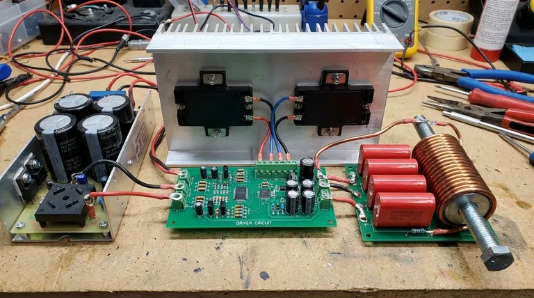
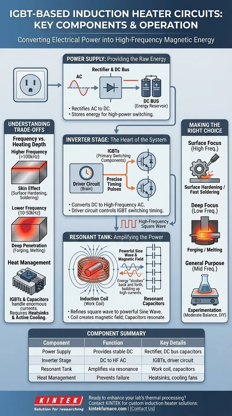
At its core, an IGBT-based induction heater is a system that converts standard electrical power into a high-frequency, high-current alternating signal. The main components are a DC power supply, an inverter stage featuring IGBTs controlled by a driver circuit, and a resonant "tank" circuit composed of the work coil and capacitors.
An induction heater isn't just a collection of parts; it's a tuned system. The goal is to create a powerful, oscillating magnetic field, and the key to achieving this efficiently is by making the work coil and a bank of capacitors resonate at a specific high frequency.
The Power Supply: Providing the Raw Energy
The entire process begins with a stable source of power. This section is responsible for taking power from the wall or a battery and conditioning it for the high-frequency inverter.
The Rectifier and DC Bus
Most induction heaters run on direct current (DC) internally, even if you plug them into an AC wall outlet. The power supply first rectifies the incoming AC into DC.
This DC voltage is then stored in large capacitors, creating what is known as a DC bus. This bus acts as a stable energy reservoir for the high-power switching that follows.
The Inverter Stage: The Heart of the System
This is where the magic happens. The inverter's job is to take the stable DC power and "chop it up" into a high-frequency AC waveform.
The IGBTs (Insulated Gate Bipolar Transistors)
The IGBTs are the primary switching components. Think of them as incredibly fast and robust electronic switches that can handle immense amounts of power.
By turning on and off thousands or even hundreds of thousands of times per second, they slice the DC from the power supply into a square wave, which is the foundational AC signal.
The Driver Circuit
The IGBTs do not decide when to switch on their own. They are controlled by a driver circuit.
This circuit is the "brain" that sends precise timing pulses to the gates of the IGBTs, telling them exactly when to open and close. The timing of these pulses determines the operating frequency of the entire heater.
The Resonant Tank: Amplifying the Power
The square wave from the IGBTs is functional, but not very efficient for heating. The resonant tank circuit refines this raw output into a powerful, clean sine wave and delivers it to the workpiece.
The Induction Coil (The Work Coil)
This is the component you see wrapped around the metal object being heated. The work coil serves two critical functions.
First, it is an inductor that, when fed with high-frequency AC, generates a powerful and rapidly changing magnetic field. This field is what induces the heating currents in your workpiece.
Second, it is one half of the resonant tank circuit. Its inductance is a key value used to calculate the circuit's resonant frequency.
The Resonant Capacitors
Paired with the work coil is a bank of high-quality capacitors. These capacitors and the coil form an "LC circuit," also known as the resonant tank.
As the IGBTs push energy into this tank, it begins to resonate, much like pushing a child on a swing at the right moment. The energy sloshes back and forth between the coil's magnetic field and the capacitors' electric fields, building up to incredibly high currents—far higher than what the power supply alone could provide.
Understanding the Trade-offs
Building or choosing an induction heater requires balancing several competing factors. The design is a series of deliberate engineering choices.
Frequency vs. Heating Depth
Higher frequencies tend to heat only the surface of a conductive material, an effect known as the skin effect. This is ideal for applications like surface hardening or soldering.
Lower frequencies allow the magnetic field to penetrate deeper into the material, resulting in more uniform, through-heating. This is necessary for applications like forging or melting a large volume of metal.
Component Ratings and Heat Management
The currents in the resonant tank can be enormous. Both the IGBTs and the resonant capacitors must be rated to handle the high voltages and currents they will experience.
Furthermore, the IGBTs generate significant waste heat during switching. Without a proper heatsink and often active fan cooling, they will quickly overheat and fail.
Making the Right Choice for Your Goal
The optimal design of an induction heater circuit depends entirely on its intended application.
- If your primary focus is surface hardening or fast soldering: You need a circuit designed for high-frequency operation (e.g., >100 kHz) to concentrate energy on the workpiece's surface.
- If your primary focus is forging or melting: You need a more robust, lower-frequency circuit (e.g., 10-50 kHz) that can drive high currents deep into the material.
- If your primary focus is general-purpose experimentation: A circuit with a moderate frequency (50-100 kHz) offers a good balance and is the most common design for DIY and benchtop units.
Ultimately, a successful induction heater is a balanced system where every component is chosen to support the goal of controlled, high-power resonance.
Summary Table:
| Component | Function | Key Details |
|---|---|---|
| Power Supply | Provides stable DC power | Includes rectifier and DC bus capacitors |
| Inverter Stage | Converts DC to high-frequency AC | Uses IGBTs and driver circuit for switching |
| Resonant Tank | Amplifies power via resonance | Comprises work coil and capacitors for efficient heating |
| Heat Management | Prevents component failure | Requires heatsinks and cooling for IGBTs |
Ready to enhance your lab's thermal processing with a custom induction heater? Leveraging exceptional R&D and in-house manufacturing, KINTEK provides diverse laboratories with advanced high-temperature furnace solutions, including IGBT-based induction heaters tailored for applications like surface hardening, forging, and melting. Our product line, featuring Muffle, Tube, Rotary Furnaces, Vacuum & Atmosphere Furnaces, and CVD/PECVD Systems, is complemented by strong deep customization capabilities to precisely meet your unique experimental needs. Contact us today to discuss how we can optimize your heating processes with reliable, high-performance equipment!
Visual Guide
Related Products
People Also Ask
- How does a vacuum hot press sintering furnace mitigate copper sintering swelling? Solve Fe-Cu Expansion Issues
- How does the vacuum environment in a vacuum hot press sintering furnace protect chromium-containing ceramics? Find out.
- Why use Vacuum Hot Press (VHP) for ZnS Ceramics? Achieve Superior IR Transparency and Mechanical Strength
- What is the core function of a vacuum hot press sintering furnace in the preparation of high-density RuTi alloys? Achieve Maximum Density and Purity
- What are the benefits of using a vacuum hot press sintering furnace for the preparation of SiCw/2024 aluminum matrix composites? Achieve High-Performance Aerospace Materials
