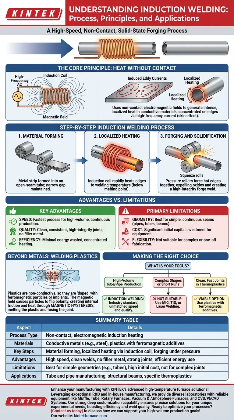
At its core, induction welding is a high-speed process that uses non-contact electromagnetic fields to generate intense, localized heat in conductive materials. Once the edges of the material reach a specific welding temperature, they are mechanically pressed together, forging them into a seamless, high-integrity joint. This method works for both metals and specially prepared plastics.
Unlike traditional welding that melts material to fill a joint, induction welding heats the base material's edges directly. This speed and precision make it the dominant technology for manufacturing tubes and pipes, creating a clean, strong weld by forging the metal in a solid state without complete melting.
The Fundamental Principle: Heat Without Contact
To truly grasp induction welding, you must first understand the physics that make it possible. The process is elegant, efficient, and relies on a few key electrical principles.
How Electromagnetic Induction Works
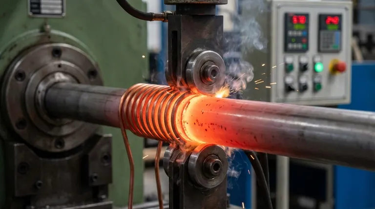
An induction welder uses a specially designed copper coil through which a high-frequency alternating current (AC) is passed. This creates a powerful and rapidly changing magnetic field around the coil.
When a conductive material, such as a steel strip, is placed within this magnetic field, the field induces strong electrical currents within the metal itself. These are known as eddy currents.
The Role of High-Frequency Current
The use of high-frequency current is critical. It causes a phenomenon known as the "skin effect," where the induced eddy currents are forced to flow in a very thin layer along the material's surface.
This concentrates the heating effect precisely where it is needed: on the two edges of the seam that are about to be joined. The result is extremely rapid and efficient heating with minimal energy wasted on the bulk of the material.
Creating a Solid-State Forge Weld
The edges are heated to a temperature where the metal becomes plastic and malleable, but typically below its actual melting point.
Immediately after heating, pressure rollers force these hot, plasticized edges together. This high-pressure forging action expels oxides and other impurities from the joint, creating a "forge weld" with a metallurgical structure that is often stronger than the original base metal.
The Step-by-Step Induction Welding Process
In a typical industrial application, like tube manufacturing, the process is continuous and highly automated.
Step 1: Material Forming
A flat metal strip is uncoiled and passed through a series of rollers that progressively form it into an open-seam tube or profile. A narrow, precise gap is maintained between the two edges.
Step 2: Localized Heating
The open-seam tube passes through the induction coil, which is positioned directly over the gap. The high-frequency magnetic field heats the two opposing edges to the target welding temperature in a fraction of a second.
Step 3: Forging and Solidification
Immediately downstream from the induction coil, a set of pressure rollers (or "squeeze rolls") forces the heated edges together under immense pressure. This completes the forge weld, and the material solidifies into a continuous, welded tube.
Understanding the Trade-offs
No process is perfect for every situation. Understanding the advantages and limitations of induction welding is crucial for proper application.
Key Advantages: Speed and Quality
The primary advantage is speed. Induction welding is one of the fastest welding processes available, making it ideal for high-volume, continuous production lines.
The process is also exceptionally clean and efficient. There is no filler metal, no slag, and minimal spatter. The resulting weld is highly consistent and free of impurities that can compromise strength.
Primary Limitations: Geometry and Cost
Induction welding is best suited for producing long, continuous seams with simple geometries, such as those found in pipes, tubes, and structural beams. It is not practical for complex joints or custom, one-off fabrication.
The initial capital investment for induction welding equipment is significant, making it more suitable for large-scale manufacturing operations where the high throughput can justify the cost.
Beyond Metals: Welding Plastics
While induction is primarily used for conductive metals, it can also be adapted to join certain types of plastics.
The Challenge of Non-Conductive Materials
Plastics are electrical insulators, so the eddy currents that heat metal cannot be induced within them. The standard induction heating process will not work.
The Solution: Magnetic Hysteresis
To overcome this, the plastic is "doped" by mixing in ferromagnetic particles or by placing a special implant at the joint.
When the assembly is placed in the magnetic field, the field rapidly flips the magnetic polarity of these particles. This constant re-orientation creates internal friction and heat through a process called magnetic hysteresis, melting the surrounding plastic and allowing the joint to be fused under pressure.
Making the Right Choice for Your Application
Use these guidelines to determine if induction welding is a fit for your project.
- If your primary focus is high-volume tube or pipe production: Induction welding is the industry standard and offers unmatched speed, quality, and cost-effectiveness at scale.
- If your primary focus is welding complex shapes or short runs: This is not the right process; traditional methods like MIG, TIG, or laser welding offer far more flexibility.
- If your primary focus is creating clean, fast joints in specific thermoplastics: Induction is a viable, high-tech option, provided you can use plastics specifically formulated with ferromagnetic additives.
By understanding its principles, you can confidently determine if this highly efficient process aligns with your manufacturing goals.
Summary Table:
| Aspect | Details |
|---|---|
| Process Type | Non-contact, electromagnetic induction heating |
| Materials | Conductive metals (e.g., steel), plastics with ferromagnetic additives |
| Key Steps | Material forming, localized heating via induction coil, forging under pressure |
| Advantages | High speed, clean welds, no filler metal, strong joints, efficient energy use |
| Limitations | Best for simple geometries (e.g., tubes), high initial cost, not for complex joints |
| Applications | Tube and pipe manufacturing, structural beams, specific thermoplastics |
Enhance your manufacturing with KINTEK's advanced high-temperature furnace solutions! Leveraging exceptional R&D and in-house manufacturing, we provide diverse laboratories with reliable equipment like Muffle, Tube, Rotary Furnaces, Vacuum & Atmosphere Furnaces, and CVD/PECVD Systems. Our strong deep customization capability ensures precise solutions for your unique experimental needs, boosting efficiency and weld quality. Ready to optimize your processes? Contact us today to discuss how we can support your high-volume production goals!
Visual Guide
Related Products
- Vacuum Induction Melting Furnace
- 600T Vacuum Induction Hot Press Vacuum Heat Treat and Sintering Furnace
People Also Ask
- What is the role of VIM and directional solidification in aero-engine blade substrates? Engineering Extreme Durability
- What are the advantages of using a Vacuum Induction Melting furnace for Cr-Si alloys? Superior Uniformity & Purity
- What are the advantages of using a VIM furnace to control residual oxygen pressure? Achieve Superior Metal Uniformity
- Why is a Vacuum Induction Melting (VIM) furnace essential? Secure Superalloy Purity and Performance
- What role does a Vacuum Induction Melting furnace play in the production of high-aluminum nickel-based superalloys?