Beyond a simple resonant tank, advanced induction heater circuits incorporate sophisticated control systems to achieve precision, efficiency, and safety. The most critical additions are closed-loop power regulation, automatic frequency tracking to maintain resonance, and a suite of protection mechanisms. These features elevate a basic heater from a brute-force tool into a highly reliable and controllable industrial or laboratory instrument.
A basic induction heater is powerful but unintelligent, often operating at maximum output with significant energy waste. Advanced features are not merely additions; they are a fundamental shift towards creating a smart system that can precisely control energy delivery, adapt to changing conditions, and protect itself from damage.
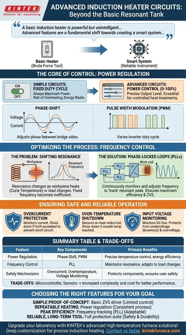
The Core of Control: Power Regulation
A primary limitation of simple induction heaters is their inability to control output power. They are either on or off. Advanced circuits solve this by actively managing the energy delivered to the work coil.
Why Simple Circuits Fall Short
Most hobbyist-level circuits, like a basic ZVS (Zero Voltage Switching) driver, run at a fixed duty cycle. This means they are always delivering maximum power, which can easily lead to overheating the workpiece, wasting energy, and offering no way to perform controlled heat treatments.
Introducing Power Control
Power regulation allows the user to set a specific output level, from 0% to 100%. This is essential for applications requiring precise temperature ramps, holding a specific temperature, or working with materials that have narrow thermal windows.
How It's Done: Phase-Shift and PWM
In advanced full-bridge or half-bridge inverters, power is most commonly controlled via phase-shifting. By adjusting the timing difference (phase) between the two sides of the bridge, the effective voltage applied to the resonant tank is changed, thus controlling the power.
Another method is Pulse Width Modulation (PWM), where the overall duty cycle of the inverter is varied to throttle the energy flow into the system.
Optimizing the Process: Frequency Control
Maximum power transfer in an induction heater occurs only when the driver's operating frequency perfectly matches the resonant frequency of the work coil and tank capacitor. Advanced circuits ensure this match is maintained automatically.
The Problem of Shifting Resonance
The resonant frequency is not static. It changes as the workpiece heats up, especially as it passes its Curie temperature and loses its magnetic properties. It also changes if you swap out the workpiece for one of a different size or material. A fixed-frequency driver will become highly inefficient as soon as conditions change.
The Solution: Phase-Locked Loops (PLLs)
The most robust solution is a Phase-Locked Loop (PLL). This is a control system that continuously monitors the phase relationship between the voltage and current in the tank circuit.
The PLL's goal is to keep this phase difference at or near zero, which signifies perfect resonance. It automatically adjusts the inverter's operating frequency in real-time to "track" the shifting resonant peak, ensuring the system is always running at maximum efficiency. This is a key component of maintaining ZVS.
Ensuring Safe and Reliable Operation
High-power electronics can fail catastrophically. Advanced induction heaters integrate multiple safety systems to protect both the circuit and the user.
Overcurrent Protection
This is the most critical safety feature. It uses a current sense transformer or a shunt resistor to constantly monitor the current flowing through the power transistors (MOSFETs or IGBTs). If the current exceeds a preset safety limit, the controller immediately shuts down the driver to prevent a short circuit from destroying the components.
Over-Temperature Shutdown
Temperature sensors are placed on the power switches' heat sinks and sometimes near the work coil. If temperatures rise above a safe operating threshold, the system will trigger a fault and shut down, preventing thermal damage.
Input Voltage Monitoring
The circuit monitors the DC bus voltage. If the input voltage sags too low (brownout) or surges too high, the controller can halt operation to protect the power supply and inverter stage from damage. This is known as undervoltage and overvoltage lockout.
Understanding the Trade-offs
Implementing these advanced features introduces complexity and cost that must be weighed against the benefits.
Complexity vs. Performance
A simple ZVS driver can be built with a handful of components. A PLL-based, power-regulated system requires a microcontroller, gate driver ICs, sense circuitry, and sophisticated firmware. This significantly increases design and debugging complexity.
The Tuning Challenge
While a PLL is powerful, it must be properly tuned. An unstable or poorly tuned PLL can fail to lock onto the resonant frequency, cause erratic behavior, or lead to hard-switching, which quickly destroys the power transistors.
Cost
The addition of a microcontroller, dedicated driver ICs, and current/temperature sensing components directly increases the bill of materials. The cost of development and programming also adds to the overall expense compared to a simple, fixed design.
Choosing the Right Features for Your Goal
The level of sophistication you need depends entirely on your application.
- If your primary focus is a simple proof-of-concept: A basic ZVS driver is sufficient to demonstrate the principles of induction heating, but expect limited control and efficiency.
- If your primary focus is repeatable heating or tempering: Implementing power regulation is non-negotiable, as it is the only way to achieve a consistent thermal process.
- If your primary focus is peak efficiency across various loads: A frequency-tracking system like a PLL is essential to adapt to different workpieces and material changes.
- If your primary focus is building a reliable, long-term tool: A full suite of overcurrent, over-temperature, and voltage protection circuits is mandatory for safety and durability.
By strategically incorporating these features, you transform a simple resonant circuit into a precise, efficient, and reliable induction heating system.
Summary Table:
| Feature | Key Components | Primary Benefits |
|---|---|---|
| Power Regulation | Phase-Shift, PWM | Precise temperature control, energy efficiency |
| Frequency Control | Phase-Locked Loop (PLL) | Maintains resonance, adapts to load changes |
| Safety Mechanisms | Overcurrent, Overtemperature, Voltage Monitoring | Protects components, ensures user safety |
| Trade-offs | Microcontroller, Sensors | Increased complexity and cost for better performance |
Upgrade your laboratory with KINTEK's advanced high-temperature furnace solutions! Leveraging exceptional R&D and in-house manufacturing, we offer Muffle, Tube, Rotary Furnaces, Vacuum & Atmosphere Furnaces, and CVD/PECVD Systems. Our strong deep customization capability ensures precise induction heating for your unique experimental needs, enhancing efficiency and reliability. Contact us today to discuss how we can tailor a solution for you!
Visual Guide
Related Products
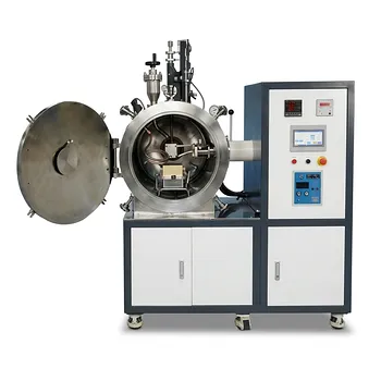
- 600T Vacuum Induction Hot Press Vacuum Heat Treat and Sintering Furnace
- Vacuum Induction Melting Furnace
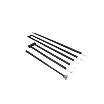
- Silicon Carbide SiC Thermal Heating Elements for Electric Furnace
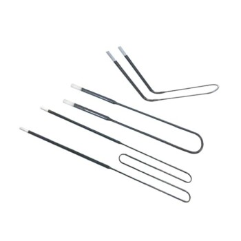
- Molybdenum Disilicide MoSi2 Thermal Heating Elements for Electric Furnace
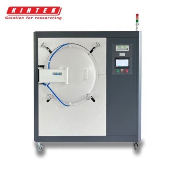
- Vacuum Heat Treat Furnace with Ceramic Fiber Liner
People Also Ask
- What are the different types of heating methods in vacuum hot press sintering furnaces? Compare Resistance vs. Induction
- What are the advantages of using a vacuum hot press sintering furnace for preparing high-density carbon nanotube reinforced copper matrix composites? Achieve Maximum Density and Purity for Superior Performance
- Why use Vacuum Hot Press (VHP) for ZnS Ceramics? Achieve Superior IR Transparency and Mechanical Strength
- How does a vacuum hot press sintering furnace mitigate copper sintering swelling? Solve Fe-Cu Expansion Issues
- What are the benefits of using a vacuum hot press sintering furnace for the preparation of SiCw/2024 aluminum matrix composites? Achieve High-Performance Aerospace Materials