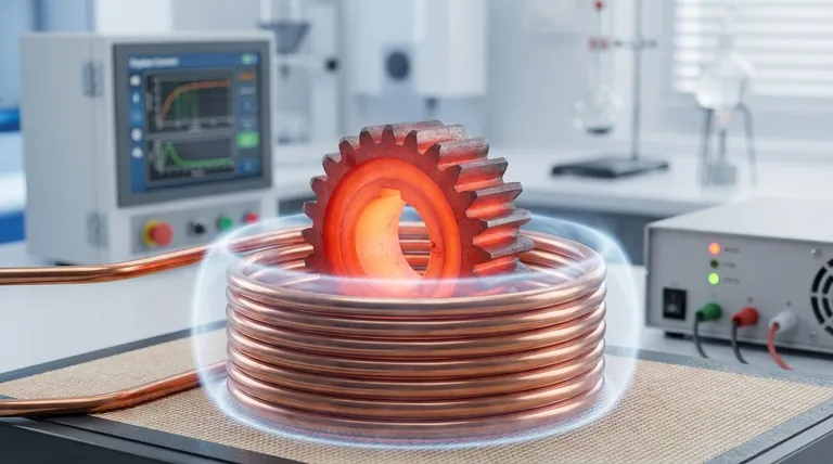
At its core, an induction heater circuit operates on the principle of electromagnetic induction. This process uses a powerful, rapidly changing magnetic field to generate heat directly within a conductive material, such as metal, without any physical contact between the heat source and the object being heated.
The central concept is transformation. The circuit transforms electrical energy into a magnetic field, and that magnetic field is then transformed back into electrical energy (in the form of eddy currents) inside the workpiece. The material's own resistance to these currents is what creates the intense, localized heat.
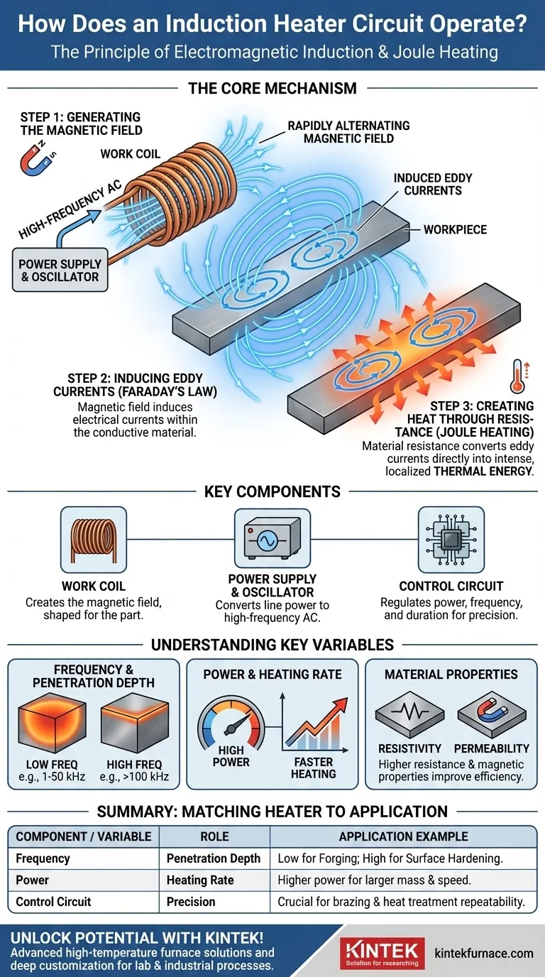
The Core Mechanism: From Magnetism to Heat
Induction heating is a multi-step process that elegantly converts electricity into precisely controlled heat. It relies on two fundamental physics principles: Faraday's Law of Induction and the Joule heating effect.
Step 1: Generating the Magnetic Field
The process begins with a specially designed work coil, typically made of copper. A high-frequency alternating current (AC) is passed through this coil.
This AC current flowing through the coil generates a powerful and rapidly alternating magnetic field in the space around and within the coil.
Step 2: Inducing Eddy Currents
When a conductive workpiece (like a steel bar) is placed inside this magnetic field, the field induces electrical currents within the metal. This is Faraday's Law of Induction in action.
These induced currents are called eddy currents. They flow in closed loops within the material, mirroring the alternating flow of current in the work coil.
Step 3: Creating Heat Through Resistance (Joule Heating)
Every conductive material has some natural electrical resistance. As the strong eddy currents flow through the workpiece, they encounter this resistance.
This opposition converts the electrical energy of the eddy currents directly into thermal energy, or heat. This phenomenon is known as Joule heating. The heat is generated inside the part itself, making the process incredibly fast and efficient.
Key Components of a Modern Induction Heater
A functional induction heating system is more than just a coil. It's a precisely controlled circuit designed to manage this energy conversion process effectively.
The Work Coil
This is the component that creates the magnetic field. Its shape and size are engineered to match the part being heated, ensuring the magnetic field is concentrated exactly where the heat is needed.
The Power Supply & Oscillator
This is the heart of the system. It takes standard line power and converts it into the high-frequency, high-amperage AC required to drive the work coil and generate the powerful magnetic field.
The Control Circuit
This is the brain of the operation. The control circuit, often using microcontrollers and sensors, regulates the power output, operating frequency, and heating duration. It allows for precise and repeatable temperature control, which is critical for industrial processes like brazing or heat treatment.
Understanding the Key Variables
The effectiveness of an induction heater is not one-size-fits-all. The design is tuned based on the specific goal, primarily by adjusting frequency and power.
The Role of Frequency
Frequency is a critical parameter that determines how deeply the heat penetrates the material.
Lower frequencies (e.g., 1-50 kHz) penetrate deeper into the metal, making them ideal for heating large, thick objects for applications like forging or melting.
Higher frequencies (e.g., 100-400 kHz and above) concentrate the heating effect on the surface of the part. This is perfect for surface hardening, brazing, or soldering where only a shallow heat-affected zone is desired.
Power and Heating Rate
The power output of the circuit directly correlates to the heating rate. Higher power induces stronger eddy currents, which generates heat much more quickly. This is adjusted based on the mass of the part and the required process time.
Material Properties
The success of induction heating also depends on the workpiece's electrical resistivity and magnetic permeability. Materials with higher resistance will heat more quickly for a given eddy current, while certain magnetic materials (like steel below its Curie temperature) heat even more efficiently due to magnetic hysteresis losses.
Matching the Heater to the Application
Understanding these principles allows you to select or design a system tailored to a specific industrial or scientific goal.
- If your primary focus is large-scale melting or through-heating for forging: You need a high-power, lower-frequency system designed for deep and uniform heat penetration.
- If your primary focus is precise surface hardening or brazing small components: You require a higher-frequency system to concentrate the energy near the surface and avoid heating the core of the part.
- If your primary focus is absolute process control and repeatability: The sophistication of the control circuit, including its temperature feedback sensors and power regulation algorithms, is the most critical factor.
By mastering the flow of energy from electricity to magnetism and finally to heat, induction heating provides an unparalleled level of speed, efficiency, and control.
Summary Table:
| Component / Variable | Role in Induction Heating |
|---|---|
| Work Coil | Generates alternating magnetic field to induce eddy currents in the workpiece |
| Power Supply & Oscillator | Converts line power to high-frequency AC for the coil |
| Control Circuit | Regulates power, frequency, and duration for precise temperature control |
| Frequency | Determines heat penetration depth (low for deep, high for surface heating) |
| Power | Controls heating rate and intensity |
| Material Properties | Affects heating efficiency based on resistivity and permeability |
Unlock the full potential of induction heating for your lab or industrial process with KINTEK! Leveraging exceptional R&D and in-house manufacturing, we provide advanced high-temperature furnace solutions tailored to your needs. Our product line includes Muffle, Tube, Rotary Furnaces, Vacuum & Atmosphere Furnaces, and CVD/PECVD Systems, all backed by strong deep customization capabilities to meet your unique experimental requirements. Contact us today to discuss how we can enhance your efficiency and precision!
Visual Guide
Related Products
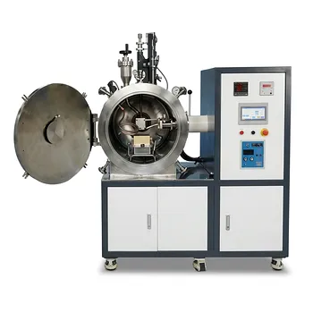
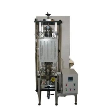
- 600T Vacuum Induction Hot Press Vacuum Heat Treat and Sintering Furnace
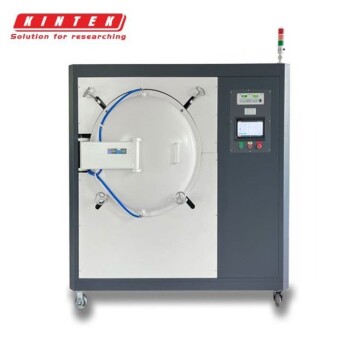
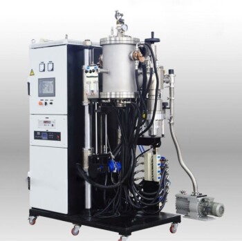
- Vacuum Induction Melting Furnace
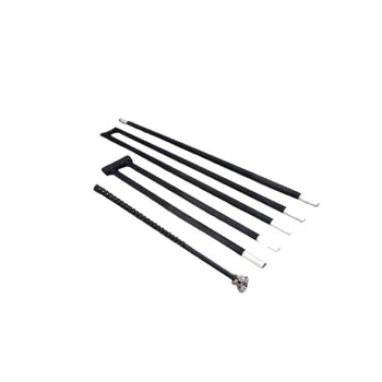
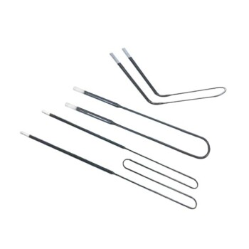
- Silicon Carbide SiC Thermal Heating Elements for Electric Furnace
- Molybdenum Disilicide MoSi2 Thermal Heating Elements for Electric Furnace
- Vacuum Heat Treat Furnace with Ceramic Fiber Liner
People Also Ask
- What are the advantages of using a vacuum hot press sintering furnace for preparing high-density carbon nanotube reinforced copper matrix composites? Achieve Maximum Density and Purity for Superior Performance
- How does a vacuum hot press sintering furnace mitigate copper sintering swelling? Solve Fe-Cu Expansion Issues
- What is the core function of a vacuum hot press sintering furnace in the preparation of high-density RuTi alloys? Achieve Maximum Density and Purity
- What is the core processing value of a vacuum hot pressing sintering furnace? Master AZ31 Magnesium Alloy Density
- How does the vacuum environment in a vacuum hot press sintering furnace protect chromium-containing ceramics? Find out.