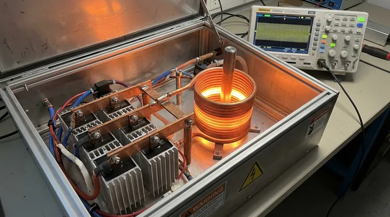
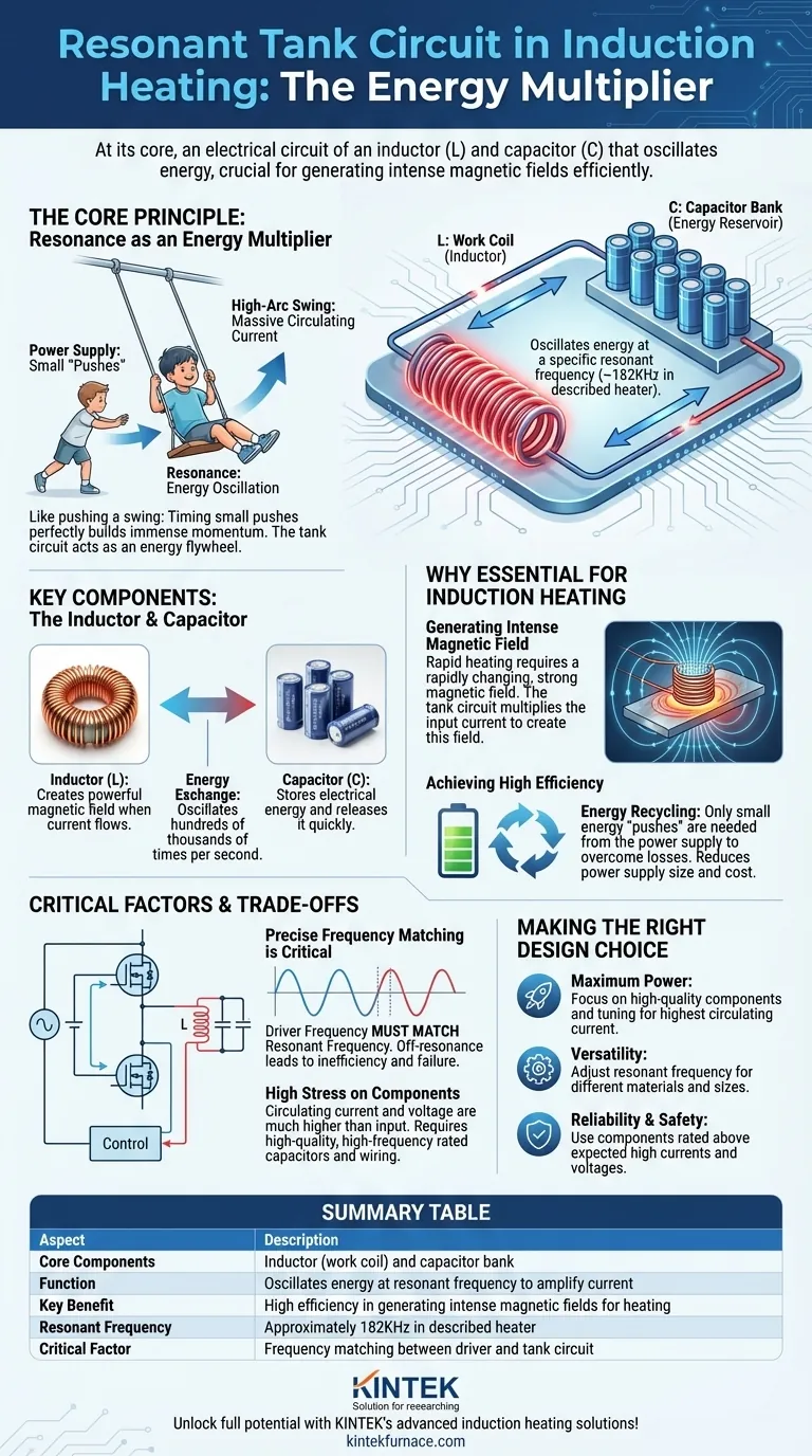
At its core, a resonant tank circuit is an electrical circuit composed of an inductor (L) and a capacitor (C) designed to oscillate energy at a specific frequency. In the described induction heater, this circuit is formed by the work coil (the inductor) and a bank of capacitors. Its purpose is to build up and circulate a massive amount of electrical energy, creating the powerful magnetic field required for efficient heating at its tuned frequency of approximately 182KHz.
The fundamental challenge of induction heating is generating an immense magnetic field without a prohibitively large power supply. The resonant tank circuit solves this by acting as an energy flywheel, storing and multiplying the input energy into a powerful internal current that makes the heating process exceptionally efficient.
The Core Principle: Resonance as an Energy Multiplier
The concept of resonance is key to understanding why a tank circuit is so effective. It allows a small, continuous input of energy to produce a very large output effect, but only at one specific frequency.
What is Resonance? An Analogy
Think of pushing a child on a swing. If you push at random times, you won't get the swing very high. But if you time your small pushes to perfectly match the natural back-and-forth rhythm of the swing, each push adds to the momentum, and the swing goes higher and higher.
In an induction heater, the power supply provides the "small pushes," and the resonant tank circuit is the "swing." The massive circulating current in the tank is the high arc of the swing.
The Key Components: The Inductor and Capacitor
The tank circuit has two essential, complementary parts.
The inductor (L) is the main work coil of the heater. Its primary job is to create a powerful magnetic field when current flows through it.
The capacitor (C) acts as a temporary energy reservoir. It stores electrical energy in an electric field and can release it very quickly.
How They Work Together: The Energy Exchange
Energy oscillates back and forth between the capacitor and the inductor hundreds of thousands of times per second.
The capacitor discharges its stored energy into the coil, creating a magnetic field. As the field collapses, it induces a current that flows back to recharge the capacitor with the opposite polarity. This cycle repeats continuously at the circuit's natural resonant frequency.
Why Resonance is Essential for Induction Heating
Without a resonant tank, building an effective induction heater would be impractical and inefficient. The tank circuit is what makes the technology viable.
Generating an Intense Magnetic Field
The rapid heating of a metal workpiece requires an extremely strong, rapidly changing magnetic field. This field, in turn, induces powerful electrical currents (eddy currents) inside the metal, which generates heat due to the material's resistance.
The resonant tank's ability to build up and circulate a current many times greater than the input current from the power supply is what creates this necessary magnetic field intensity.
Achieving High Efficiency
The tank circuit is a master of energy recycling. Once oscillating, it only needs small "pushes" of energy from the power supply to make up for heat lost in the components (resistive losses).
This means the power supply doesn't need to provide the full, massive current circulating in the tank. This dramatically reduces the size and cost of the power supply and makes the entire system far more efficient.
The Role of the Control Circuit
The control circuit is the "brains" of the operation. It drives the power transistors (like MOSFETs) to switch on and off at a frequency that precisely matches the resonant frequency of the tank circuit.
This synchronized switching is what provides the timely "pushes" to the swing, ensuring maximum energy is transferred into the tank circuit to sustain the oscillation.
Understanding the Trade-offs and Pitfalls
While powerful, resonant circuits demand careful design and an understanding of their limitations to ensure a safe and reliable system.
The Critical Need to Match Frequency
The system is only efficient when the driver frequency from the control circuit perfectly matches the tank's natural resonant frequency.
If the frequencies are mismatched, power transfer plummets. This is known as operating "off-resonance." It can cause excessive heat and electrical stress in the power supply components, potentially leading to failure.
High Stress on Components
The circulating current and voltage inside a resonant tank can be many times higher than the input levels. This places extreme stress on the inductor and especially the capacitors.
Using cheap, low-quality capacitors is a common point of failure. The capacitors must be specifically rated for high-frequency, high-current resonant applications to avoid overheating and catastrophic failure.
Making the Right Choice for Your Goal
Understanding the tank circuit's function allows you to make better design decisions based on your specific objective.
- If your primary focus is maximum heating power: Your goal is to achieve the highest possible circulating current by using high-quality, low-loss components and ensuring your driver is perfectly tuned to the tank's resonant frequency.
- If your primary focus is heating different materials or sizes: You must design a system where you can adjust the resonant frequency (by changing the capacitance or coil inductance) to optimally match the properties of each new workpiece.
- If your primary focus is reliability and safety: You must prioritize using capacitors and wiring rated well above the expected currents and voltages in the tank circuit, as resonance will multiply these values significantly.
By mastering the principles of the resonant tank circuit, you unlock the full potential for efficient and powerful induction heating.
Summary Table:
| Aspect | Description |
|---|---|
| Core Components | Inductor (work coil) and capacitor bank |
| Function | Oscillates energy at resonant frequency to amplify current |
| Key Benefit | High efficiency in generating intense magnetic fields for heating |
| Resonant Frequency | Approximately 182KHz in the described heater |
| Critical Factor | Frequency matching between driver and tank circuit |
Unlock the full potential of your induction heating with KINTEK's advanced solutions! Leveraging exceptional R&D and in-house manufacturing, we provide diverse laboratories with high-temperature furnace systems like Muffle, Tube, Rotary, Vacuum & Atmosphere Furnaces, and CVD/PECVD Systems. Our strong deep customization capability ensures precise alignment with your unique experimental needs, enhancing efficiency and reliability. Contact us today to discuss how we can support your projects!
Visual Guide
Related Products
- 600T Vacuum Induction Hot Press Vacuum Heat Treat and Sintering Furnace
- Vacuum Induction Melting Furnace
- Multi Heating Zones CVD Tube Furnace Machine for Chemical Vapor Deposition Equipment
- Silicon Carbide SiC Thermal Heating Elements for Electric Furnace
- Molybdenum Disilicide MoSi2 Thermal Heating Elements for Electric Furnace
People Also Ask
- Why use Vacuum Hot Press (VHP) for ZnS Ceramics? Achieve Superior IR Transparency and Mechanical Strength
- What are the benefits of using a vacuum hot press sintering furnace for the preparation of SiCw/2024 aluminum matrix composites? Achieve High-Performance Aerospace Materials
- What are the different types of heating methods in vacuum hot press sintering furnaces? Compare Resistance vs. Induction
- How does the vacuum environment in a vacuum hot press sintering furnace protect chromium-containing ceramics? Find out.
- How does a vacuum hot press sintering furnace mitigate copper sintering swelling? Solve Fe-Cu Expansion Issues