The stability of an IGBT module is fundamentally linked to its temperature coefficient of resistivity. A flat, or slightly positive, temperature coefficient means the device's on-state resistance remains highly consistent or increases slightly as its temperature rises. This characteristic is the key to ensuring predictable performance, preventing catastrophic failure modes, and enhancing the overall reliability of high-power electronic systems.
The most significant advantage of a flat temperature coefficient is its ability to enable safe and stable parallel operation of multiple IGBTs. This property creates a natural self-balancing mechanism that prevents thermal runaway, a critical failure mode in high-current applications.
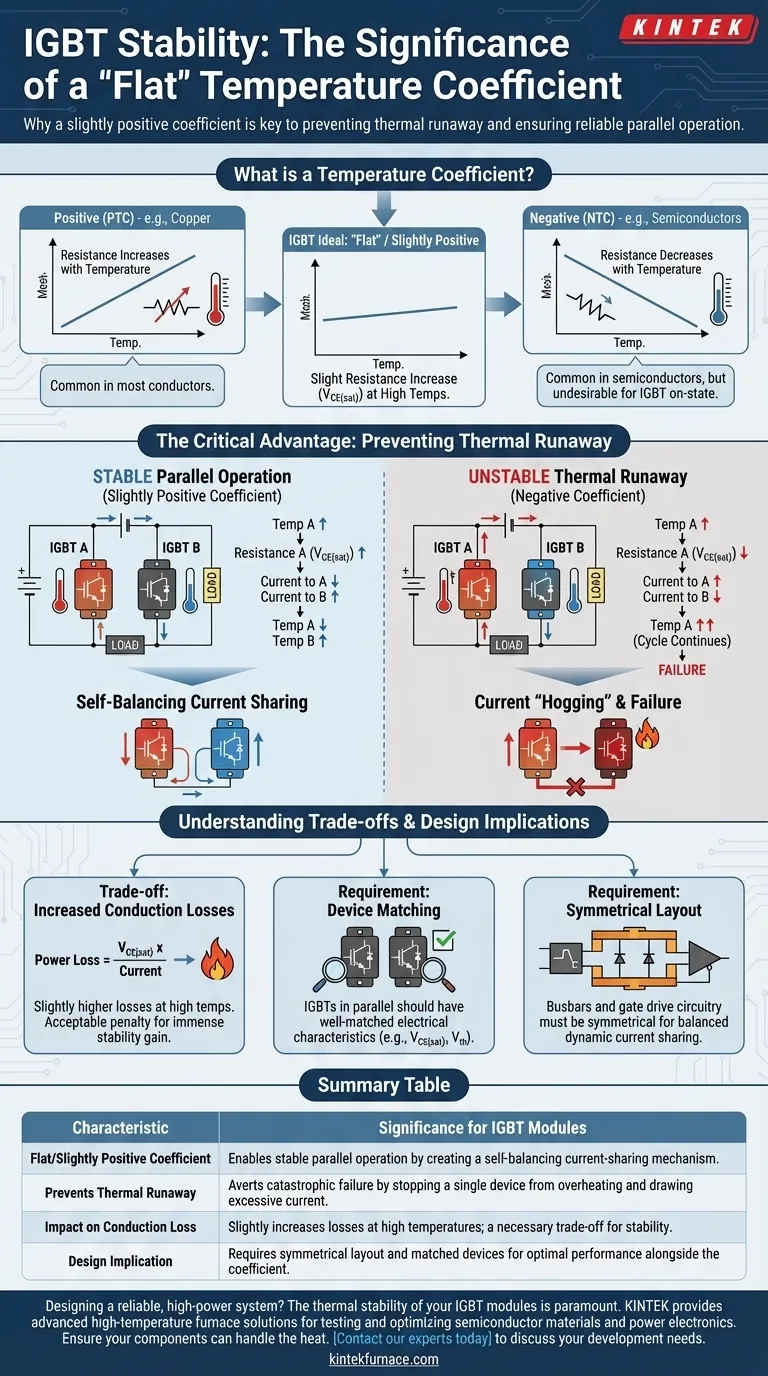
What is a Temperature Coefficient?
Defining the Coefficient
The temperature coefficient of resistivity describes how a material's electrical resistance changes with temperature.
A positive temperature coefficient (PTC) means resistance increases as temperature increases. Most conductors, like copper, exhibit this behavior.
A negative temperature coefficient (NTC) means resistance decreases as temperature increases. This is common in semiconductors. However, for an IGBT's on-state resistance, a PTC is highly desirable.
The Ideal "Flat" Characteristic in IGBTs
When we refer to a "flat" coefficient in an IGBT, we are specifically talking about the on-state collector-emitter saturation voltage, or V_CE(sat).
"Flat" is engineering shorthand for a slightly positive temperature coefficient. This means as the IGBT heats up during operation, its on-state resistance and V_CE(sat) increase by a small, predictable amount. This seemingly minor detail has major implications for system design.
The Critical Advantage: Preventing Thermal Runaway
The Challenge of Current Sharing
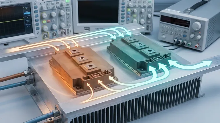
High-power applications, such as large motor drives or grid-tied inverters, often require more current than a single IGBT can handle. The solution is to connect multiple IGBT modules in parallel.
The primary challenge in this design is ensuring all parallel devices share the total current equally. If one IGBT carries significantly more current than the others, it will overheat and fail, potentially causing a cascading failure of the entire system.
How a Positive Coefficient Creates Stability
A slightly positive temperature coefficient provides an elegant, passive solution to this problem. It creates a self-regulating feedback loop.
Imagine two IGBTs in parallel. If one device (IGBT A) begins to get hotter than its neighbor (IGBT B), its on-state resistance (V_CE(sat)) will increase slightly. Because current follows the path of least resistance, a small amount of current will naturally divert from the hotter IGBT A to the cooler IGBT B.
This diversion of current cools IGBT A and slightly warms IGBT B, automatically balancing the thermal load between them. This prevents any single device from "hogging" current and overheating.
The Danger of a Negative Coefficient
If an IGBT had a negative temperature coefficient, the opposite would happen. A device that starts to get hotter would see its resistance decrease.
This would cause it to draw more current, which in turn would make it even hotter. This vicious cycle, known as thermal runaway, would continue until the device is destroyed. A flat or slightly positive coefficient is the primary defense against this failure mode.
Understanding the Trade-offs
Conduction Losses Will Increase Slightly
The primary trade-off of a positive temperature coefficient is a minor increase in conduction losses at higher operating temperatures. Since conduction loss is calculated as Power Loss = V_CE(sat) * Current, a higher V_CE(sat) at high temperatures results in more heat being generated.
This is a well-understood and acceptable trade-off. The immense gain in system stability and the prevention of thermal runaway far outweigh the small penalty in efficiency. This effect must simply be factored into the thermal management design.
Device Matching is Still Important
While the positive temperature coefficient provides automatic balancing, it doesn't eliminate the need for good engineering practices. For optimal performance, the IGBTs used in parallel should still be well-matched in their electrical characteristics, particularly the threshold voltage and V_CE(sat).
Furthermore, the physical layout of the busbars and gate drive circuitry must be symmetrical to ensure equal impedances, which helps with balanced current sharing during the fast switching transitions.
How This Influences Your Design Choices
Choosing the right component is about matching its characteristics to your system's goals.
- If your primary focus is high-power reliability: Prioritize IGBT modules with a documented flat or slightly positive temperature coefficient for V_CE(sat) to guarantee safe parallel operation.
- If your primary focus is thermal management: Your design must account for the slight increase in conduction losses at the maximum expected operating temperature to ensure your cooling system is adequate.
- If your primary focus is building a robust system: Do not rely solely on the IGBT's properties; ensure your gate driver circuit and busbar layout are symmetrical to promote balanced dynamic and static current sharing.
Understanding this fundamental property allows you to design power electronic systems that are not only powerful but also inherently stable and reliable.
Summary Table:
| Characteristic | Significance for IGBT Modules |
|---|---|
| Flat/Slightly Positive Coefficient | Enables stable parallel operation by creating a self-balancing current-sharing mechanism. |
| Prevents Thermal Runaway | Averts catastrophic failure by stopping a single device from overheating and drawing excessive current. |
| Impact on Conduction Loss | Slightly increases losses at high temperatures; a necessary trade-off for stability. |
| Design Implication | Requires symmetrical layout and matched devices for optimal performance alongside the coefficient. |
Designing a reliable, high-power system? The thermal stability of your IGBT modules is paramount. At KINTEK, we leverage our exceptional R&D and in-house manufacturing to provide advanced high-temperature furnace solutions, including specialized systems for testing and optimizing semiconductor materials and power electronics. Our deep customization capabilities allow us to precisely meet your unique R&D and production requirements.
Ensure your components can handle the heat. Contact our experts today to discuss how we can support your development of stable and robust power systems.
Visual Guide